Locking and unlocking mechanism assembly for charging

A technology of adding an unlocking and locking mechanism, applied in the field of quick battery replacement, which can solve the problems of high price of small motors, large horizontal and vertical dimensions, limited output torque, etc., to meet the load requirements of quick battery replacement and facilitate promotion Application, the effect of reducing the overall cost

Pending Publication Date: 2019-12-24
BOZHON PRECISION IND TECH CO LTD
View PDF0 Cites 15 Cited by
  • Summary
  • Abstract
  • Description
  • Claims
  • Application Information

AI Technical Summary

Problems solved by technology

[0003] Although a variety of power replacement methods have appeared at present, such as using the tightening gun to tighten the shaft for tightening, locking or unlocking, although the performance is reliable and the control is flexible, the servo motor is often used to cooperate with the reduction mechanism to realize the rotation drive, but the horizontal size of this type of structure is different from that of The vertical dimension is huge, such as using a small motor, the price is high, and the output torque is limited

Method used


Image

  • Locking and unlocking mechanism assembly for charging
  • Locking and unlocking mechanism assembly for charging
  • Locking and unlocking mechanism assembly for charging

Examples


Embodiment 1

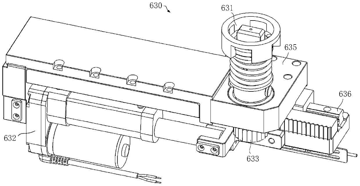
[0083] Embodiment 1. Rotate and unlock the main body 630:

[0084] Such as Figure 3-9 As shown, the rotary unlocking body 630 includes an unlocking assembly 631, a linear drive assembly 632, and a transmission structure; among them,

[0085] The unlocking assembly 631 includes an unlocking ring 6311, an unlocking rotary block 6314; the unlocking ring 6311 abuts the locking mechanism of the battery assembly and provides thrust for unlocking the locking mechanism of the battery assembly; the unlocking rotary block 6314 is used to provide a driving locking mechanism The torque of rotation; the unlocking ring 6311 is a hollow structure, and the unlocking ring 6311 is set outside the unlocking rotary block 6314;

[0086] The transmission structure is used to connect the linear drive assembly 632 and the unlocking and unlocking assembly 631. The transmission structure converts the linear motion into a rotary motion, so that the linear drive assembly 632 drives the unlocking rotary block 6...

Embodiment 2

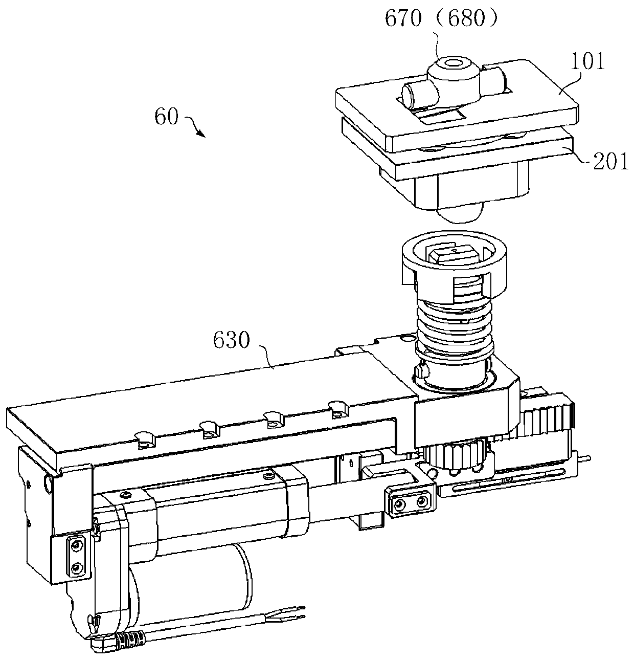
[0093] Embodiment 2. The first locking mechanism body 670:

[0094] The locking mechanism is the first locking mechanism body 670, such as figure 1 As shown, the first locking mechanism body 670 is mounted on the battery substrate 201 of the battery assembly, while the first locking shaft 671 passes through the vehicle bottom substrate 101, and the first locking shaft 671 rotates to realize the battery assembly and the vehicle The quick lock and unlock.

[0095] Such as Figure 10-19 As shown, the first locking mechanism body 670 includes a first locking rotating shaft 671, a first locking pin 672, a first limiting housing, and a limiting member 675; wherein,

[0096] The first locking pin 672 is fixed through one end of the first locking rotating shaft 671, and the other end of the first locking rotating shaft 671 is used to contact the unlocking rotating block 6314;

[0097] The limiting member 675 is partially or fully placed in the limiting housing, and the first locking shaft 671...

Embodiment 3

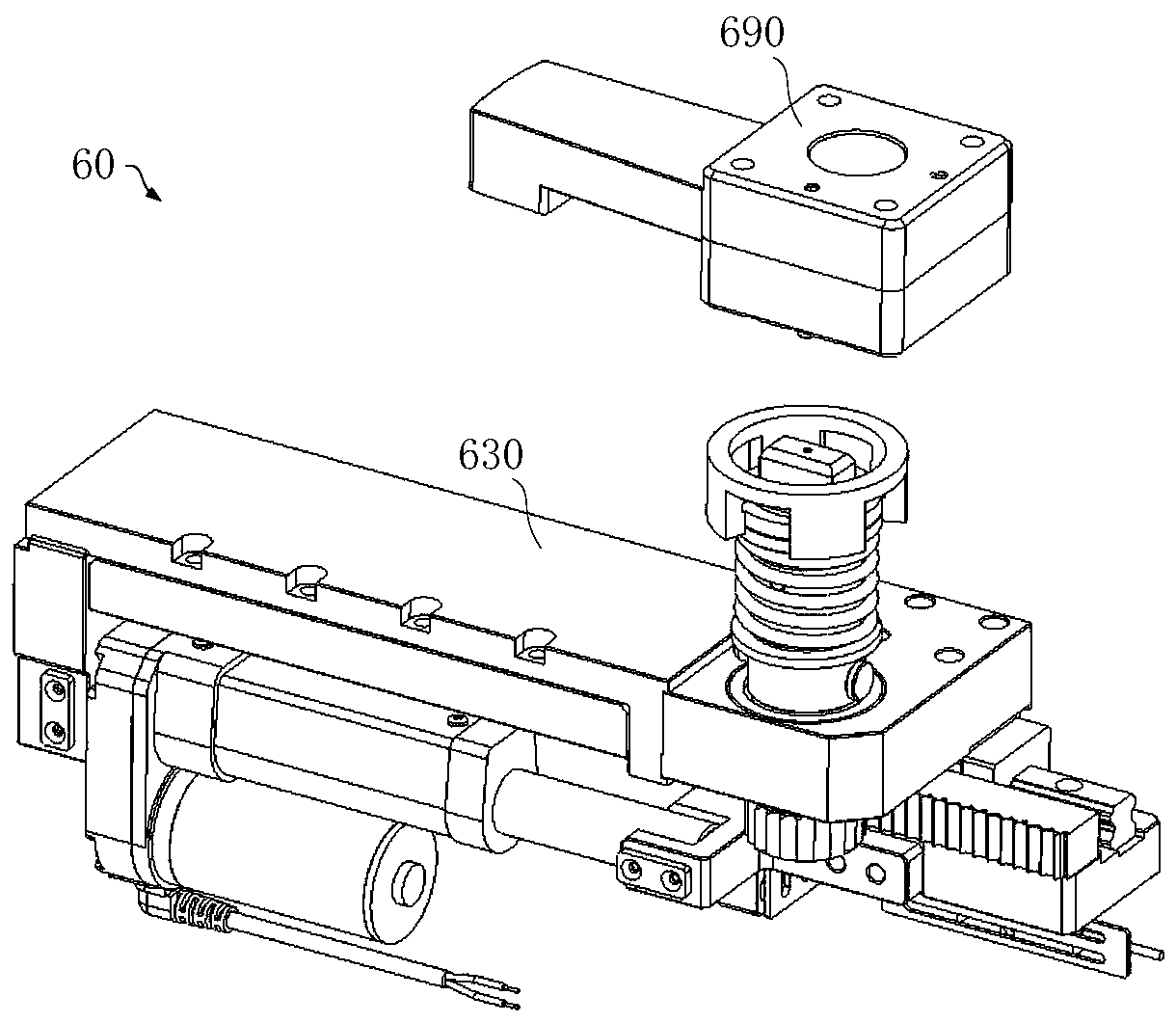
[0110] Embodiment 3. The second locking mechanism body 680:

[0111] The locking mechanism is the second locking mechanism body 680, such as figure 1 As shown, the second locking mechanism body 680 is mounted on the battery substrate 201 of the battery assembly, and the first locking shaft 671 passes through the vehicle bottom substrate 101 of the vehicle, and rotates through the second locking shaft 681 to realize the battery assembly and the vehicle The quick lock and unlock.

[0112] Such as Figure 20-30 As shown, the second locking mechanism body 680 includes a second locking shaft 681, a second locking pin 682, a second limiting housing, a limiting block 685, an elastic member 687, and a thrust ring 688;

[0113] The second locking pin 682 is fixed through one end of the second locking shaft 681, and the other end of the second locking shaft 681 is used to contact the rotating power assembly; the second locking pin 682 is used to rotate to lock or unlock the battery assembly;

...


PUM


Abstract

The invention provides a locking and unlocking mechanism assembly for charging. The locking and unlocking mechanism assembly for charging comprises a locking mechanism and a rotating unlocking body. The locking mechanism is used for locking or unlocking a battery assembly, so that the battery assembly and a car body are fixed or separated; the rotating unlocking body comprises a locking and unlocking assembly, a linear drive assembly and a transmission structure; the locking and unlocking assembly is used for being abutted against the locking mechanism and providing a pushing force for unlocking the locking mechanism so as to provide a torque for driving the locking mechanism to rotate; the transmission structure is used for connecting the linear drive assembly and the locking and unlocking assembly, and converting linear motion into rotation motion; and the linear drive assembly drives the unlocking assembly to act on the locking mechanism through the transmission structure, so that the battery assembly is locked or unlocked. The locking and unlocking mechanism assembly for charging provided by the invention is ingenious in structure and reasonable in design; and the linear drivedevice is adopted as a power source, so that no speed reduction structure is needed, and the overall cost is effectively reduced; and meanwhile, the transmission manner is accurate and reliable, so that a load requirement of quick charging of a new energy vehicle is met, and the locking and unlocking mechanism assembly for charging is convenient to popularize and apply.

Description

Technical field [0001] The invention belongs to the field of quick battery replacement, and specifically relates to an unlocking mechanism assembly for power replacement. Background technique [0002] With the increasing use of various types of new energy vehicles such as electric vehicles and hybrid vehicles, technologies related to battery quick change have become more and more subjects of concern and research. [0003] Although there have been a variety of power exchange methods, such as the use of a tightening gun to tighten the shaft for tightening, locking or unlocking, although the performance is reliable and the control is flexible, servo motors are often used with deceleration mechanisms to achieve rotation drive, but the horizontal size of such structures The vertical size is huge, such as the use of small motors are expensive, and the output torque is limited. [0004] In this regard, there is an urgent need to improve the existing rotary unlocking device to solve the abo...

Claims


Application Information

Patent Timeline
Patent Type & Authority Applications(China)
IPC IPC(8): B60S5/06
CPCB60S5/06
Inventor 牟东戴有发孔超群吴小平孙庆
Owner BOZHON PRECISION IND TECH CO LTD
Why Eureka
Try Eureka