Real-time monitoring system and method for concrete vibration

A real-time monitoring and concrete technology, which is applied in the direction of measuring devices, instruments, and measuring ultrasonic/sonic/infrasonic waves, etc., can solve the problems of affecting signal sending and receiving, not being accurate enough, and unable to cover the whole area of ​​vibration monitoring, etc., to achieve flexible and limited networking small effect

Active Publication Date: 2019-12-24
上海中兴思秸通讯有限公司
View PDF11 Cites 12 Cited by
  • Summary
  • Abstract
  • Description
  • Claims
  • Application Information

AI Technical Summary

Problems solved by technology

[0003] The main problems in the concrete vibrating process are: the vibrating process is not quantified, it depends on the personal quality of the construction personnel, and the construction quality of the vibrating process cannot be guaranteed
This system has the following shortcomings: it is only suitable for vibrating the trolley, but in practice, manual vibration is generally used; the accuracy of GPS positioning equipment is limited, and the radius of action of the vibrating rod is basically 0.5 In this case, it is difficult to achieve relatively accurate positioning; the various sensors used in the system are all traditional point sensors, and there is a common problem that they cannot cover the entire vibration monitoring area
This system has the following disadvantages: the process of transmitting and receiving signals cannot represent the working process of the vibrator, that is, when the vibrator is in an idle state in the working area, there will be signals sent and received, and this system cannot accurately collect To the working status information of the vibrator; various complex construction environments may affect the sending and receiving of signals
The disadvantage of this method is that all the vibrators need to be modified, and it is very inflexible to use
The disadvantage of this method is: the accuracy of GPS is not enough to meet the positioning requirements of the vibrator; the positioning signal of GPS is greatly affected by the environment, and human walking, steel frames and templates on the construction site will interfere with the positioning signal; This method needs to transform all vibrating rods, which is not flexible enough; it is not accurate enough to judge the quality of vibrating only by the duration of vibrating

Method used


Image

  • Real-time monitoring system and method for concrete vibration

Examples


Embodiment Construction

[0035] The present invention will be further described in detail through the accompanying drawings and specific embodiments below.

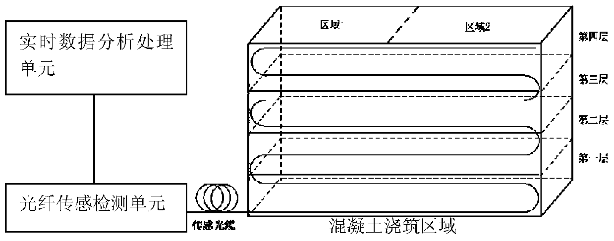
[0036] As shown in the figure, a real-time monitoring system for concrete vibration of the present invention includes a real-time data analysis and processing unit, an optical fiber sensing detection unit connected to the real-time data analysis and processing unit, and a sensing optical fiber connected to the optical fiber sensing detection unit .

[0037] The sensing optical fiber is arranged in the concrete pouring area, and is laid along the steel bar extension direction of the concrete steel bar frame. Such as figure 1 As shown, the sensing optical fiber in this embodiment is laid in a reciprocating manner, the concrete pouring area is divided into several pouring layers distributed up and down in units of layers, and the sensing optical fiber passes through all the pouring layers.

[0038] There are temperature sensing fibers and vibration ...


PUM


Abstract

The invention discloses a real-time monitoring system for concrete vibration, and the system comprises a real-time data analysis and processing unit, an optical fiber sensing and detecting unit, and asensing optical fiber, wherein the sensing optical fiber is arranged in a concrete pouring area, and the optical fiber sensing and detecting unit is configured to receive an optical signal sent by the sensing optical fiber and analyze the optical signal to obtain vibration data including at least the optical fiber; the real-time data analysis and processing unit is configured to analyze the vibration data to obtain at least the vibration position information of a vibration rod. The invention also discloses a real-time monitoring method for concrete vibration, which is implemented by the system described above. By adopting the above technical solution, the optical fiber is used as a sensor to replace the original point sensor, which has flexible networking and small limitations, and can meet the vibration monitoring in various complex environments. The distributed optical fiber sensing technology can be used to obtain more accurate and reliable vibrating monitoring results than traditional methods, and can quickly adapt to the construction site environment with no need to modify the vibrating rod.

Description

technical field [0001] The invention relates to a concrete vibrating real-time monitoring system and method, belonging to the technical field of concrete construction. Background technique [0002] In the construction of roads, bridges, tunnels, etc., there will be a lot of air in the concrete after mixing, transportation and pouring into the mold. Filled with concrete without creating voids. Therefore, the principle of vibratory liquefaction is used to vibrate the poured concrete to increase its fluidity after liquefaction and fill the entire formwork, so that the concrete particles are closely combined, and the air trapped inside the concrete is discharged from the surface of the concrete, thereby To achieve dense and firm concrete. The greater the amount of concrete pouring, the more air bubbles, the greater the void ratio, and the poorer the compactness. Only through vibration can the problem of concrete compactness be solved. It is to ensure that the concrete is compa...

Claims


Application Information

Patent Timeline
Patent Type & Authority Applications(China)
IPC IPC(8): G01D21/02G01H9/00G01B11/00
CPCG01B11/00G01D21/02G01H9/004
Inventor 江平孙畅伍伟刘博陈章豪林向东张亮
Owner 上海中兴思秸通讯有限公司
Why Eureka
Try Eureka