Power stage stimulation driving system and method for permanent magnet synchronous motors

A permanent magnet synchronous motor and drive system technology, used in motor generator testing, power metering, measuring electricity, etc., can solve problems such as inability to simulate complex and changeable, and achieve the effect of reducing energy loss and facilitating early fault diagnosis.

Active Publication Date: 2019-12-24
SHANGHAI UNIV
View PDF10 Cites 10 Cited by
  • Summary
  • Abstract
  • Description
  • Claims
  • Application Information

AI Technical Summary

Problems solved by technology

[0007] In view of the inability to simulate complex and changeable working conditions in the traditional inverter testing process and the defects of existing motor simulation methods, the purpose of the present invention is to propose a power level simulation drive system and method for permanent magnet synchronous motors, eliminating the need for It eliminates the real motor and mechanical load in the traditional inverter test process, and at the same time greatly reduces the energy loss in the test process

Method used


Image

  • Power stage stimulation driving system and method for permanent magnet synchronous motors
  • Power stage stimulation driving system and method for permanent magnet synchronous motors
  • Power stage stimulation driving system and method for permanent magnet synchronous motors

Examples


Embodiment 1

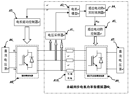
[0054] Embodiment one: see figure 1 , the power stage simulation drive system of the permanent magnet synchronous motor, including the permanent magnet synchronous motor power stage simulator (A0), the motor drive controller (A3), the DC voltage source (A6) and the drive side converter (A8), all The DC voltage source (A6) is electrically connected to a permanent magnet synchronous motor power stage simulator (A0) through a driving side converter (A8), and the permanent magnet synchronous motor simulator (A0) is driven by the motor drive controller (A3) Side converter (A8) control.

Embodiment 2

[0055] Embodiment 2: This embodiment is basically the same as Embodiment 1, and the special features are as follows:

[0056] The permanent magnet synchronous motor power stage simulator (A0) comprises a motor model (A2) via an induced electromotive force real-time controller (A4), an induced electromotive force controller (A5) and is electrically connected to an induced electromotive force control side converter (A9 ); the induced electromotive force control side converter (A9) is electrically connected to a DC voltage source (A7), and is electrically connected to the drive side converter (A8) and a voltage sampler (A1) via a resistor network (A10) ; The voltage sampler (A1) is connected to the motor model (A2).

Embodiment 3

[0057] Embodiment 3: The power level simulation driving method of the permanent magnet synchronous motor is operated by using the above-mentioned system, including the following steps:

[0058] 1) Obtain the voltage signal of the three-phase port of the power stage simulator of the permanent magnet synchronous motor;

[0059] 2) The sampled voltage signal is input into the motor model to calculate the operating state of the simulated permanent magnet synchronous motor;

[0060] 3) Feedback the operating state of the permanent magnet synchronous motor to the motor driver and the real-time observer of the induced electromotive force;

[0061] 4) The motor driver controls the power stage simulator of the permanent magnet synchronous motor according to the operating state of the simulated permanent magnet synchronous motor fed back, thereby simulating the input current of the drive system to the motor simulator;

[0062] 5) The induced electromotive force observer generates the p...


PUM


Abstract

The present invention relates to a power stage stimulation driving system and method for permanent magnet synchronous motors. The system comprises two bidirectional power converters, voltage samplingof three-phase ports of a drive-side converter, a motor model, a motor drive controller, a real-time induced electromotive force observer, an induced electromotive force controller, a DC voltage source, and a resistance network. According to the system and method provided by the present invention, the induced electromotive force of the permanent magnet synchronous motor can be simulated, and the steady-state and transient simulation of the electrical and mechanical behaviors of various permanent magnet synchronous motors can be realized through the combined effect of the resistance network andthe power converters; and the system provides a simulation test environment close to the real working condition for early fault diagnosis, performance evaluation under the extreme condition, and aging testing of converters used in the field of motor drive, real motors and mechanical loads are eliminated, test efficiency is improved, and the waste of energy is avoided.

Description

technical field [0001] The invention relates to the fields of power electronics technology and motor drive, and more specifically, to a power-level simulation drive system and method of a permanent magnet synchronous motor. Background technique [0002] Permanent Magnet Synchronous Motor (PMSM) is widely used in AC drive systems due to its advantages of simple structure, small torque ripple coefficient, fast dynamic response, high power density, and low loss. With the continuous expansion of the application field of the drive system based on the AC permanent magnet synchronous motor, its working conditions become more and more complicated. In the AC drive system, the drive inverter largely determines the efficiency and reliability of the entire system, so it is a must to test the inverter close to the actual working conditions during the development process and before delivery. essential link. [0003] Most of the traditional inverter testing methods are to connect the inv...

Claims


Application Information

Patent Timeline
Patent Type & Authority Applications(China)
IPC IPC(8): G01R31/34G01L3/24
CPCG01R31/343G01L3/24
Inventor 王爽李波赵剑飞
Owner SHANGHAI UNIV
Why Eureka
Try Eureka