Display module and its full bonding method

A display module, full lamination technology, applied in identification devices, instruments, calculations, etc., can solve the problems of easy generation of air bubbles, entering the interior of the display module, etc., to achieve the effect of improving the bubble phenomenon

Active Publication Date: 2021-07-23
WUHAN CHINA STAR OPTOELECTRONICS TECH CO LTD
View PDF9 Cites 0 Cited by
  • Summary
  • Abstract
  • Description
  • Claims
  • Application Information

AI Technical Summary

Problems solved by technology

[0005] This disclosure provides a display module and its full lamination method, which solves the problems of air bubbles that are easily generated at the junction of the visible area and the ink area of ​​the cover plate when the cover plate and the display panel of the existing display module are fully laminated. The technical problem that external water vapor easily enters the interior of the display module from the side

Method used


Image

  • Display module and its full bonding method
  • Display module and its full bonding method
  • Display module and its full bonding method

Examples


Embodiment 1

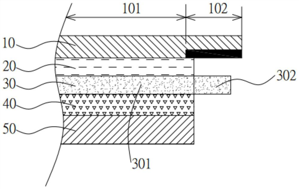
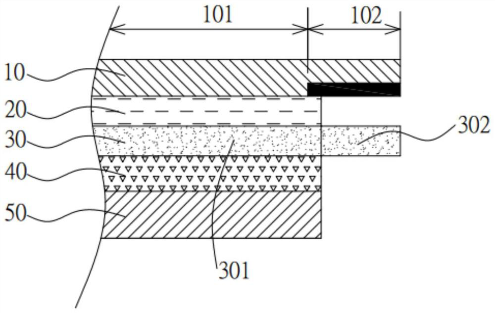
[0037] Such as figure 1 Shown is a schematic cross-sectional structure diagram of a display module provided by an embodiment of the present disclosure. The display module includes a cover plate 10 , a glass substrate 20 , a display panel 50 and an adhesive layer 30 .

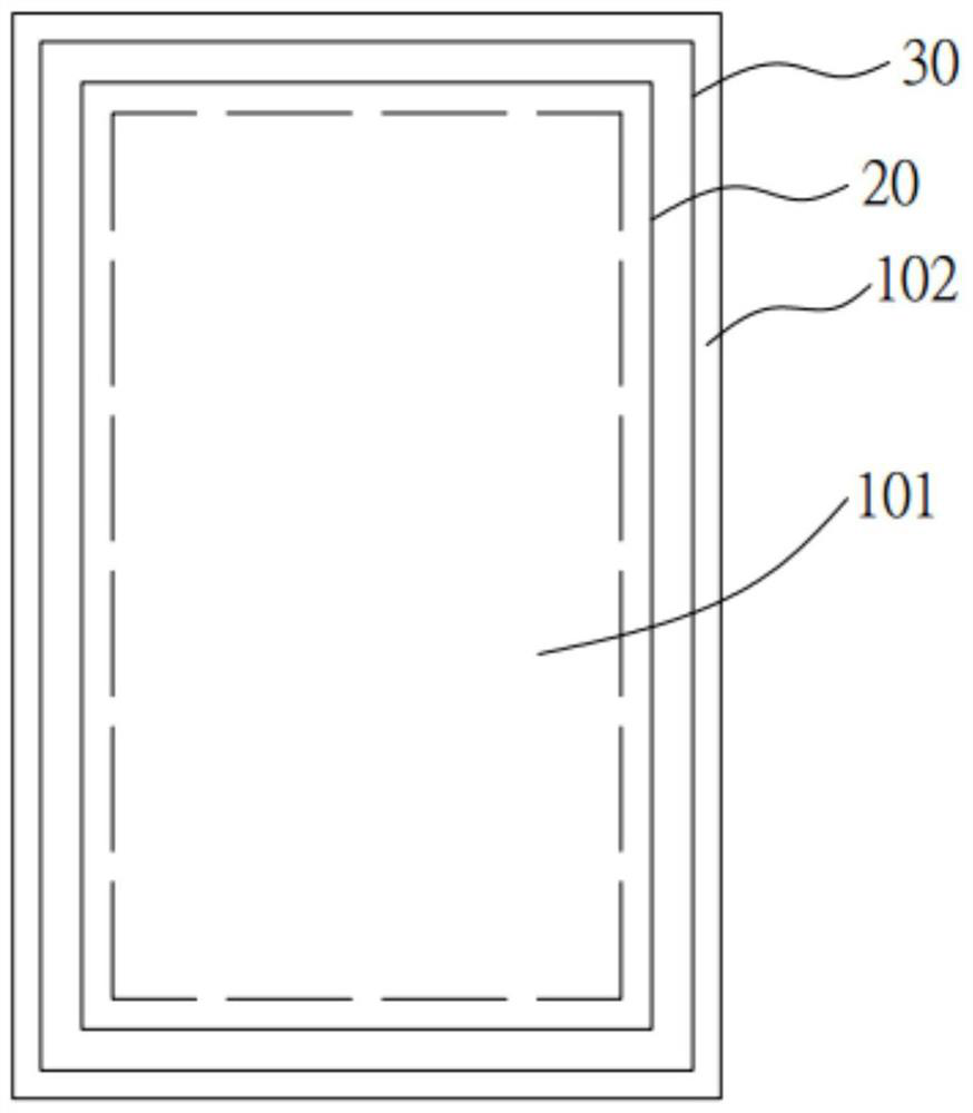
[0038] Wherein, the cover plate 10 includes a visible area 101 and an ink area 102 surrounding the visible area, the visible area 101 is used to display images, and the ink area 102 is an opaque area.

[0039] The glass substrate 20 is combined with the cover plate 10, and its periphery is superposed to the ink area 102, that is to say, the outer edge of the glass substrate 20 corresponds to the ink area 102. It should be noted that , the outer edges are defined for the inner and outer sides of the display module.

[0040] The display panel 50 is located on the side of the glass substrate 20 away from the cover plate 10, and the display panel 50 can be a liquid crystal display panel, or an organic light-emittin...

Embodiment 2

[0050] Such as Figure 5 As shown, the full lamination method of the display module provided by the embodiment of the present disclosure includes the following steps:

[0051] Step S10: Under a vacuum environment, attach the adhesive layer 30 to the cover plate 10 combined with the glass substrate 20 in position;

[0052] Specifically, the cover plate 10 includes a visualization area 101 and an ink area 102, the glass substrate 20 is bonded to the cover plate 10, and its periphery is superimposed to the ink area 102 of the cover plate 10; The adhesive layer is UV-OCA optical glue.

[0053] Step S20: Under a vacuum environment, align and attach the cover plate 10 and the display panel 50 together;

[0054] Step S30: performing a defoaming treatment on the adhesive layer 30;

[0055] Specifically, the in-plane degassing is carried out under low temperature and low pressure conditions, wherein the conditions of one degassing treatment are: the temperature is controlled within ...


PUM


Abstract

The disclosure provides a display module and its full bonding method. The display module includes a cover plate, a glass substrate, a display panel and an adhesive layer, wherein the cover plate includes a visualization area and an ink area surrounding the visualization area; the glass substrate is combined On the cover plate, its outer edge corresponds to the ink area; the display panel is located on the side of the glass cover plate away from the cover plate; the adhesive layer is arranged between the glass substrate and the display panel, including the main body part and the outer expansion part, and the outer expansion part Located on the peripheral edge of the main body, the orthographic projection of the outer edge of the expanded part on the glass substrate is located outside the glass substrate. By expanding the optical glue beyond the glass substrate and performing side UV curing on the display module, the expanded Part of the optical glue on the glass substrate is cured to prevent impurities such as external water vapor from entering the display module, and through two defoaming treatments, it can effectively improve the phenomenon of air bubbles at the junction of the visible area and the ink area of ​​the cover plate of blind hole products.

Description

technical field [0001] The disclosure relates to the field of display technology, and in particular to a display module and a full bonding method thereof. Background technique [0002] Full lamination refers specifically to the process of fully laminating the touch screen and display in the touch display industry. Using the full lamination process can make the screen look more transparent, enhance the display effect of the screen, and protect screen to isolate it from foreign objects. [0003] The existing display module is a full-fit connection between the cover plate and the display panel. The cover plate includes the visualization area (VA) and the ink area (BM). Blind hole products refer to opening holes on the polarizer. The defoaming requirements in the inner area are inconsistent, so that the overall air bubbles of the blind hole product cannot be completed through a single defoaming process. Moreover, in the full lamination production, the adhesive material is usual...

Claims


Application Information

Patent Timeline
Patent Type & Authority Patents(China)
IPC IPC(8): G09F9/00G06F3/041
CPCG06F3/041G09F9/00
Inventor 余朋飞宋涛屠桂朋
Owner WUHAN CHINA STAR OPTOELECTRONICS TECH CO LTD
Why Eureka
Try Eureka