
Improved saturable reactance transformer

A technology of reactive transformers and transformer units, applied in the direction of variable transformers, transformers, variable inductors, etc.

Inactive Publication Date: 2019-12-24
江苏康宇电力设备有限公司
View PDF4 Cites 0 Cited by
  • Summary
  • Abstract
  • Description
  • Claims
  • Application Information

AI Technical Summary

Problems solved by technology

[0007] In view of the above, an object of the present invention is to devise a transformer structure capable of overcoming the difficulties encountered with existing transformer systems and allowing the use of variable reactance transformers at high loads, especially in three-phase connected the case

Method used


Image

  • Improved saturable reactance transformer
  • Improved saturable reactance transformer
  • Improved saturable reactance transformer

Examples


Embodiment Construction

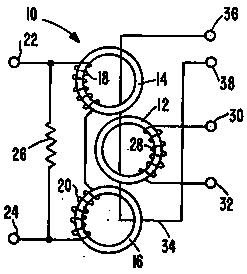
[0021] Turning now to a more detailed consideration of the invention, in figure 1 shown in . figure 1 is a variable reactance transformer comprising a main core 12 and two auxiliary cores 14 and 16. These cores are toroidal and constructed of suitable magnetic material, the proportions of which are such that the auxiliary cores 14 and 16 can become saturated underneath. Normal range of DC control current effects. Neither the auxiliary core nor the main core necessarily exhibit what is known as a "square loop hysteresis curve", but are preferably conventional magnetic materials.

[0022] Auxiliary cores 14 and 16 carry control windings 18 and 20 respectively, which are connected in series to a variable DC control current source connected to terminals 22 and 24 . The series arrangement of control windings is shunted by a suitable impedance such as resistor 26 . Primary core 12 carries secondary winding 28 which provides a controlled output voltage between terminals 30 and 32 ...


PUM


Abstract

The invention discloses an improved saturable reactance transformer, which is provided with a main core and a pair of adjacent auxiliary cores. The auxiliary magnetic cores are provided with DC control windings which adjust the reactance of the main magnetic core bearing a secondary or output winding of the transformer. A primary winding is wound on the three magnetic cores to control the output of the voltage regulation secondary winding. In order to prevent high-voltage stress in the transformer, each control winding is divided into two or more windings, and the windings are concentrically wound on a common magnetic core so as to reduce the voltage caused by the alternating current in the primary winding. The windings on the two auxiliary cores are connected in pairs in a crossed mannerto balance the induced voltage. The transformer adopts a physical structure, and the primary winding and the control windings are started at the same position, so that the voltage difference between the end points of the control windings and the end point of the primary winding is reduced, and the voltage stress insulation applied to the transformer is reduced. Each control winding of the transformer is connected to a corresponding variable control source, so as to reduce the induction of the primary alternating current to the high stress voltages in the control windings.

Description

technical field [0001] The present invention relates generally to improved variable reactance transformers and, more particularly, to a variable reactance transformer construction which permits the use of transformers in three-phase delta configuration without stress faults. Background technique [0002] Controllable transformers which exploit the saturation effect of direct current to obtain controllable output voltage and current are known in the art, and one such transformer is disclosed in US Patent No. 5,199,072. U.S. Patent No. 3,343,074 issued September 19, 1967 to Elwood M. Brock. In this patent, a variable reactance transformer is shown with three toroidal, concentrically arranged cores carrying control, primary and secondary windings formed as toroids on the cores. Each of the two outer or auxiliary cores carries the DC winding, the center or main core carries the secondary winding, and the primary winding surrounds all three cores. The DC winding is connected in...

Claims


Application Information

Patent Timeline
IPC IPC(8): H01F27/28H01F27/29H01F27/40H01F27/24H01F29/02
CPCH01F27/24H01F27/28H01F27/29H01F27/40H01F29/02H01F29/025
Inventor 于龙飞
Owner 江苏康宇电力设备有限公司
Learn More