High-temperature oil frying machine

A frying machine and high-temperature technology, which is applied in food forming, food science, application, etc., can solve the health hazards of operators and other problems, achieve uniform frying, avoid burns, and ensure health effects

Active Publication Date: 2019-12-27
湖南恒森农业科技股份有限公司
View PDF6 Cites 2 Cited by
  • Summary
  • Abstract
  • Description
  • Claims
  • Application Information

AI Technical Summary

Problems solved by technology

[0004] The purpose of the present invention is to provide a high-temperature frying machine to solve the problem caused by the cooking fume during the frying process of the high-temperature frying machine proposed in the above-mentioned background technology. health hazard issues

Method used


Image

  • High-temperature oil frying machine
  • High-temperature oil frying machine
  • High-temperature oil frying machine

Examples


Embodiment 1

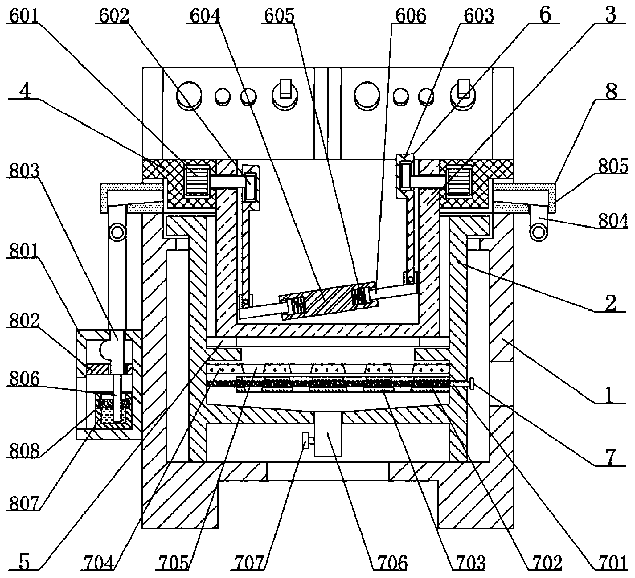
[0026] See figure 1 , image 3 , Figure 4 with Figure 5 , The present invention provides a technical solution:

[0027] A high-temperature fryer includes a fryer 1, a shaking device 6, a separating device 7 and a processing device 8. An oil cylinder 2 is arranged on the inside of the fryer 1, and the oil cylinder 2 is slidingly connected to the fryer 1, and the top of the inner side of the oil cylinder 2 There is a frying screen 3, the oil tank 2 is slidingly connected with the frying screen 3, the top of the outside of the frying screen 3 is fixedly connected with a bracket 4, the bracket 4 is slidingly connected with the fryer 1 and the oil tank 2, and the bottom end of the frying screen 3 is slidingly connected with heating The assembly 5, the heating assembly 5 is slidably connected with the oil cylinder 2, a shaking device 6 is provided inside the frying screen 3, and the shaking device 6 is fixedly connected with the bracket 4, the shaking device 6 includes a first motor ...

Embodiment 2

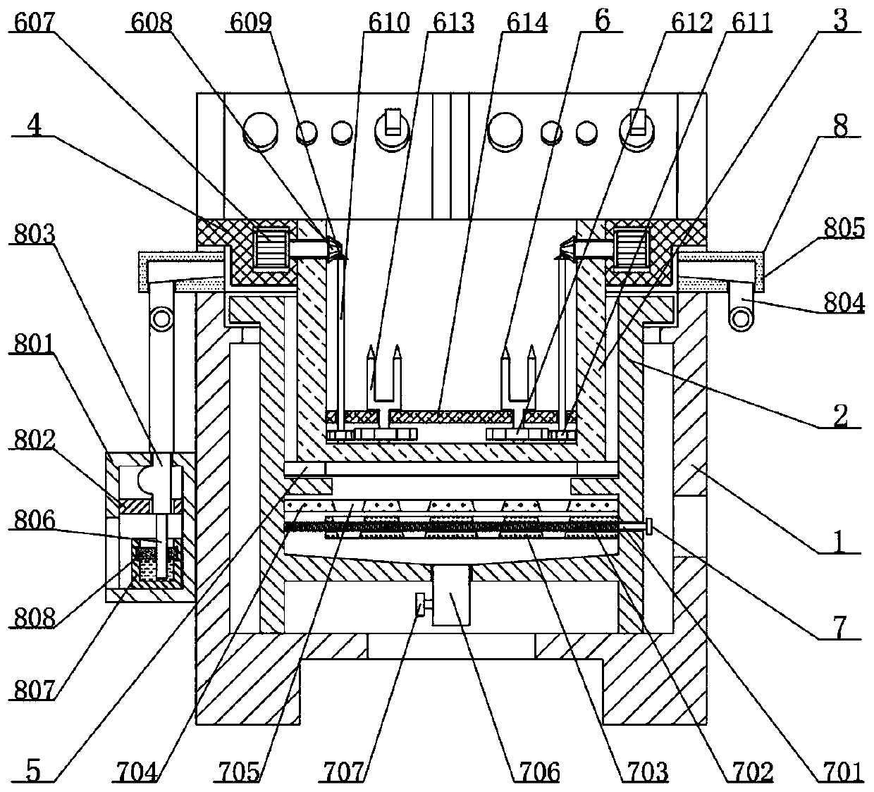
[0031] See figure 2 , image 3 with Figure 4 , The present invention provides a technical solution:

[0032] A high-temperature fryer includes a fryer 1, a shaking device 6, a separating device 7 and a processing device 8. An oil cylinder 2 is arranged on the inner side of the fryer 1, and the oil cylinder 2 is slidingly connected to the fryer 1, and the inner top of the oil cylinder 2 There is a frying screen 3, the oil tank 2 is slidingly connected with the frying screen 3, the top of the outside of the frying screen 3 is fixedly connected with a bracket 4, the bracket 4 is slidingly connected with the fryer 1 and the oil tank 2, and the bottom end of the frying screen 3 is slidingly connected with heating Component 5, the heating component 5 is slidably connected with the oil cylinder 2, a shaking device 6 is provided inside the frying screen 3, and the shaking device 6 is fixedly connected to the bracket 4, the shaking device 6 includes a second motor 607, a driving bevel ge...


PUM


Abstract

The invention relates to the technical field of oil frying machines and in particular to a high-temperature oil frying machine which comprises an oil frying machine, a shaking device, a separating device and a processing device, wherein an oil cylinder is arranged on the inner side of the oil frying machine; the oil cylinder is in sliding connection with the oil frying machine; a frying sieve is arranged at the top end of the inner side of the oil cylinder; the oil cylinder is in sliding connection with the frying sieve; a support block is fixedly connected with the top end of the outer side of the frying sieve; the support block is in sliding connection with the oil frying machine and the oil cylinder; a heating component is in sliding connection with the bottom end surface of the fryingsieve; the heating component is in sliding connection with the oil cylinder; and the shaking device is arranged on the inner side of the frying sieve. Due to adoption of a gas collecting frame, and together with communication of the gas collection frame and a gas inlet tube, sliding connection of a gas outlet tube and a water absorption sponge layer and sliding connection of the water absorption sponge layer and a glass cup, oil fume generated in frying can be adsorbed when the device is used, so that not only is the health of operators ensured, but also the oil fume treatment cost can be lowered.

Description

Technical field [0001] The invention relates to the technical field of frying machines, in particular to a high-temperature frying machine. Background technique [0002] The frying machine has electric heating, coal heating, gas heating and other methods. It is a multifunctional, oil-water mixed frying equipment. The single-machine series is suitable for all kinds of small and medium-sized food factories and fast food restaurants with large production. Chicken shops and pastry shops, etc., can fry a variety of fried foods, but most of the operations still rely on human hands-on operations. The main energy sources are liquefied gas and natural gas. With the continuous development of society, oil There are more and more types of fryer, but some high-temperature fryer may have some defects when in use. Therefore, the demand for a high-temperature fryer is increasing. [0003] In the field of frying machines, some of the frying machines currently in use cannot well absorb the oil fume...

Claims


Application Information

Patent Timeline
Patent Type & Authority Applications(China)
IPC IPC(8): A23L5/10A23P30/00
CPCA23L5/11A23L5/12A23P30/00Y02P60/80
Inventor 张勤
Owner 湖南恒森农业科技股份有限公司
Why Eureka
Try Eureka