
Device and method for emission pulse interleave synchronous signal of pulse system radar

A technology for synchronizing signals and signals, applied in measurement devices, utilizing re-radiation, reflection/re-radiation of radio waves, etc., can solve the problem of increased system control software complexity, system hardware complexity, and the number of pulse synchronization signals that can be inserted. limited issues

Active Publication Date: 2019-12-27
INST OF ELECTRONICS CHINESE ACAD OF SCI
View PDF5 Cites 2 Cited by
  • Summary
  • Abstract
  • Description
  • Claims
  • Application Information

AI Technical Summary

Problems solved by technology

[0008] Although the first device for generating pulse synchronization signals saves hardware costs, its main technical defects include: the system’s normal pulse chirp signal transmission is interrupted, which will affect the continuity of the SAR system’s ground imaging; in order to ensure that the SAR system has sufficient A number of normal pulse signals are sent to the ground, and the number of pulse synchronization signals that can be inserted during the working hours of the system is limited, which cannot make the phase synchronization between the two stars reach a higher level
[0009] Although the second device for generating pulse synchronization signals can flexibly insert pulse synchronization signals between the transmission pulses of uninterrupted pulse chirp signals, its main technical defects include: the complexity of the system hardware increases, and a new pulse synchronization signal is added. The synchronous signal generation device needs to add circuit boards, devices, boxes, hardware interfaces, cables and corresponding environmental tests, and the cost will increase accordingly; the complexity of the system control software will increase, and it is necessary to add new components for the pulse synchronous signal generation device. Mode Control Script and Timing Control

Method used


Image

  • Device and method for emission pulse interleave synchronous signal of pulse system radar
  • Device and method for emission pulse interleave synchronous signal of pulse system radar
  • Device and method for emission pulse interleave synchronous signal of pulse system radar

Examples


Embodiment Construction

[0049] In order to understand the characteristics and technical contents of the embodiments of the present invention in more detail, the implementation of the embodiments of the present invention will be described in detail below in conjunction with the accompanying drawings. The attached drawings are only for reference and description, and are not intended to limit the embodiments of the present invention.

[0050] In the description of the embodiments of the present application, it should be noted that unless otherwise stated and limited, the term "connection" should be understood in a broad sense, for example, it can be an electrical connection, it can also be the internal communication of two components, and it can be a direct connection , can also be indirectly connected through an intermediary, and those of ordinary skill in the art can understand the specific meanings of the above terms according to specific situations.

[0051] It should be noted that the term "first\se...


PUM


Abstract

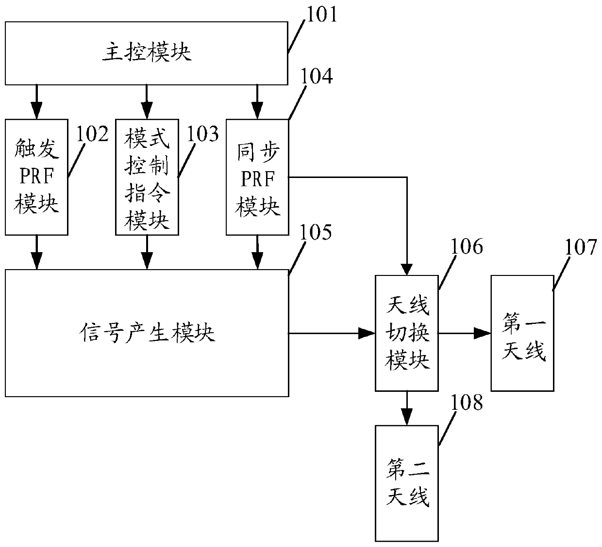
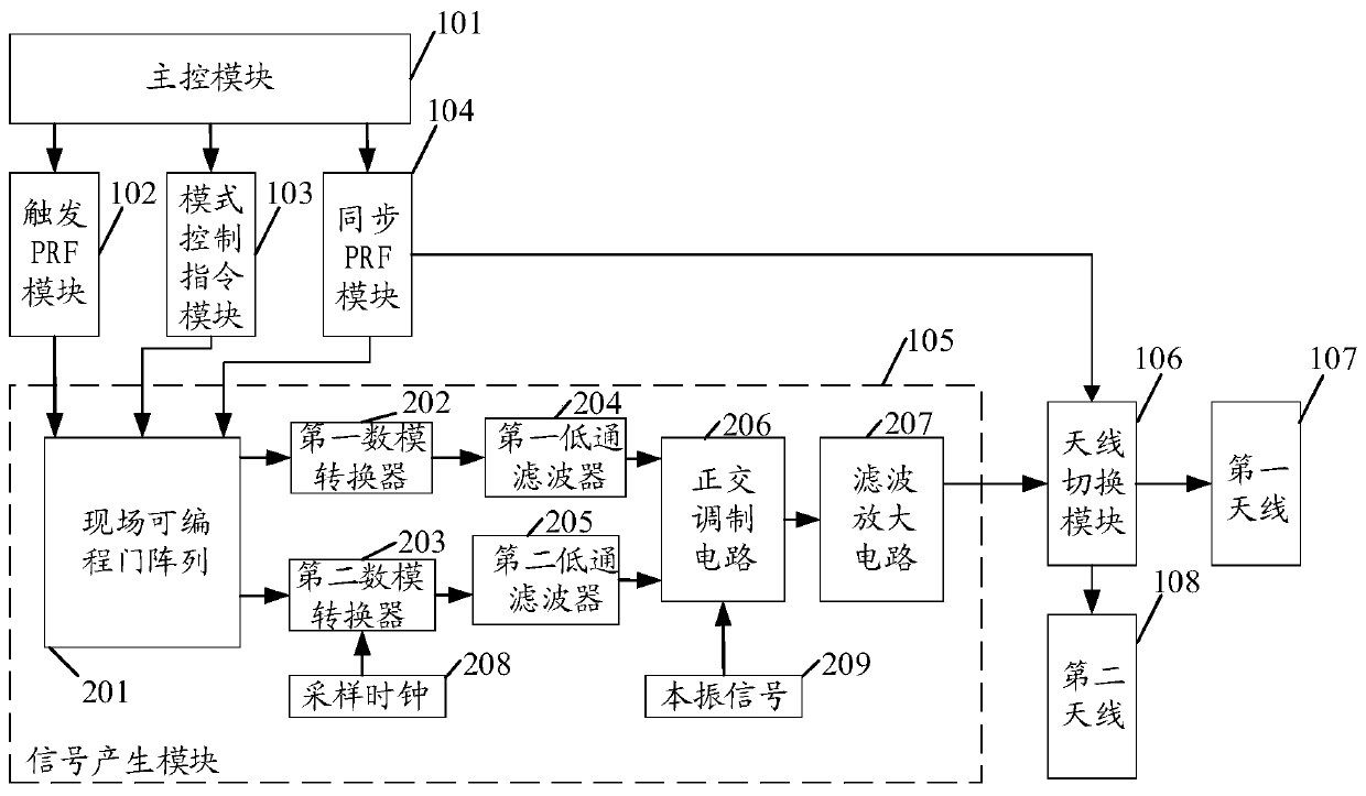
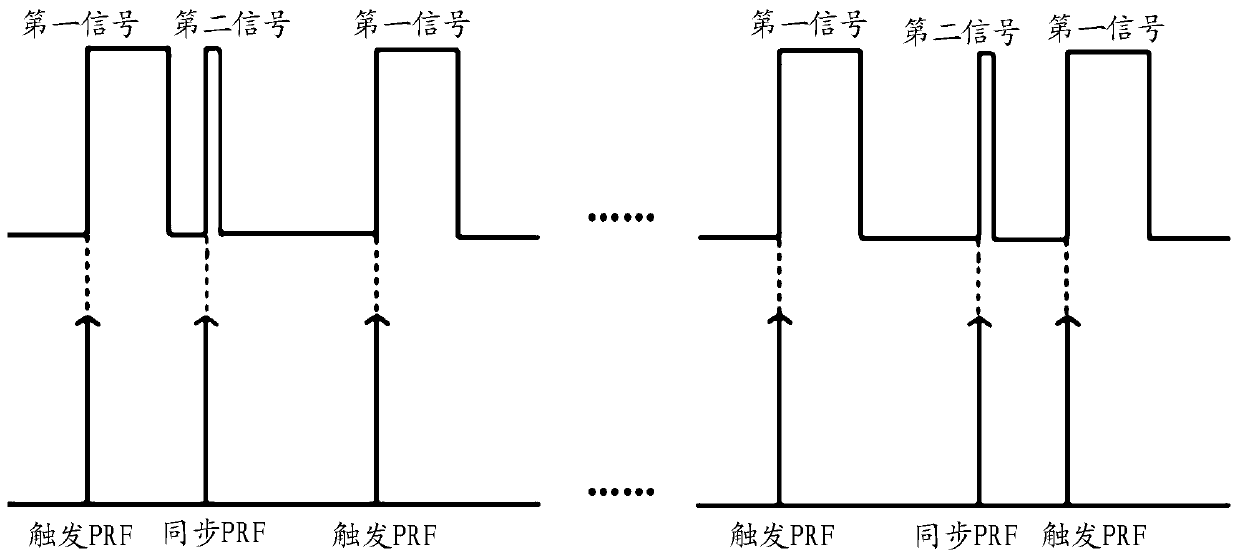
The invention discloses a device for an emission pulse interleave synchronous signal of a pulse system radar. The device comprises a master control module, a trigger pulse repeated frequency (PRF) module, a mode control instruction module, a synchronous PRF module, a signal generation module, an antenna switching module, a first antenna and a second antenna. The first antenna or the second antennais grated through controlling the antenna switching module by synchronous PRF sent from the synchronous PRF module, a first signal is sent by the first antenna when trigger PRF received by the signalgeneration module is a first level, a second signal is sent by the second antenna when synchronous PRF received by the signal generation module is the first level, and the technical effect of the emission pulse interleave synchronous signal is achieved. The invention also discloses a method for the emission pulse interleave synchronous signal of the pulse system radar.

Description

technical field [0001] The invention relates to the technical field of space-borne synthetic aperture radar signal generation, in particular to a device and method for pulse system radar to insert synchronization signals between pulses. Background technique [0002] With the rapid development of spaceborne Synthetic Aperture Radar (SAR) systems, high resolution, multi-band, multi-polarization, multi-mode and interference have become the main directions for countries to concentrate their efforts to overcome difficulties. Among them, interference is the A hot area. [0003] The conventional spaceborne SAR system is a single-satellite single-antenna pulse system radar. According to a certain pulse repetition frequency (Pulse Repeating Frequency, PRF), it transmits a chirp signal with a certain pulse width and bandwidth, receives and records the echo data, and downloads it to the ground. Signal processing and imaging are performed on the ground. The disadvantage of the convent...

Claims


Application Information

Patent Timeline
IPC IPC(8): G01S7/282G01S13/90
CPCG01S7/282G01S13/90G01S13/9023
Inventor 岳义崴沙瑜刘开雨王宇
Owner INST OF ELECTRONICS CHINESE ACAD OF SCI
Learn More