Stainless steel pipe cutting device

A technology for cutting devices and stainless steel pipes, applied in the direction of pipe shearing devices, shearing devices, shearing machines, etc., can solve the problems of low work efficiency, steel pipe transportation deviation, etc., and achieve the effect of simple structure

Active Publication Date: 2019-12-31
佛山力肇金属制品有限公司
View PDF15 Cites 5 Cited by
  • Summary
  • Abstract
  • Description
  • Claims
  • Application Information

AI Technical Summary

Problems solved by technology

[0003] The purpose of the present invention is to provide a stainless steel pipe cutting device in view of the technical problem that the steel pipe transportation of the existing stainless steel pipe cutting machine is easy to shift and cause low work efficiency

Method used


Image

  • Stainless steel pipe cutting device

Examples


Embodiment Construction

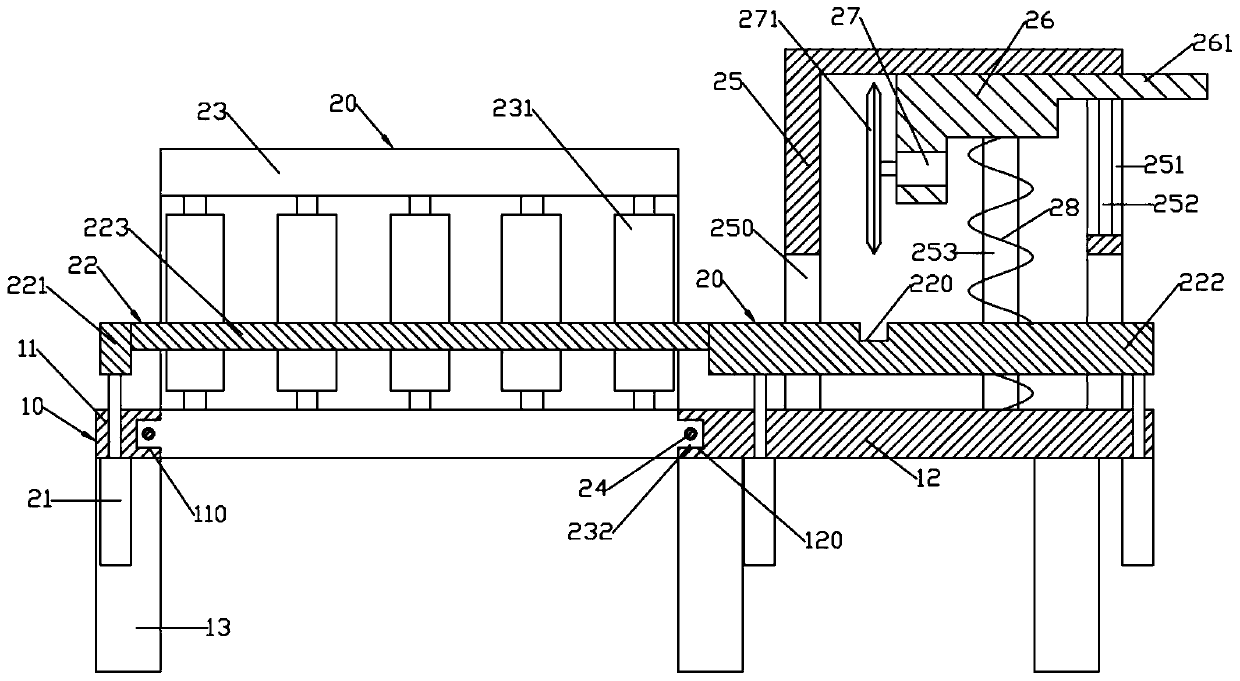
[0014] Such as figure 1 As shown, a stainless steel pipe cutting device includes a supporting workbench 10 and a delivery cutting device 20; the supporting workbench 10 includes a left support plate 11 and a right support plate 12; the bottom surfaces of the left support plate 11 and the right support plate 12 are all installed There are a number of evenly distributed support feet 13; the conveying and cutting device 20 includes a conveying device; the conveying device includes a pair of "凵"-shaped conveying support seats 23 and a lifting support plate 22; a pair of conveying support seats 23 have openings opposite to each other; The support base 23 is moved back and forth between the left support plate 11 and the right support plate 12 and is moved away from or close to each other synchronously; between a pair of vertically symmetrical horizontal parts of the transport support base 23, a number of uniformly distributed transport rollers 231 are arranged in rotation; Lifting s...


PUM


Abstract

The invention discloses a stainless steel pipe cutting device. The stainless steel pipe cutting device comprises a supporting workbench and a conveying and cutting device; the supporting workbench comprises a left supporting plate and a right supporting plate; the conveying and cutting device comprises a conveying device; the conveying device comprises a pair of U-shaped conveying support bases and a lifting support plate; openings of the pair of conveying support bases are opposite front and back; the pair of conveying support bases are arranged between the left supporting plate and the rightsupporting plate in a front-back moving manner and are synchronously far away from each other or close to each other; a plurality of conveying rollers which are evenly distributed left and right arerotatably arranged between a pair of vertically symmetrical horizontal portions of the conveying support bases; the lifting support plate is arranged over the supporting workbench in a lifting manner;the lifting support plate is composed of a left lifting support plate located at the left end, a middle supporting rod located in the middle and a right lifting support plate located at the right end; and a cutting device is arranged on the right supporting plate.

Description

technical field [0001] The invention relates to the technical field of stainless steel processing, in particular to a stainless steel pipe cutting device. Background technique [0002] The existing stainless steel pipe cutting machine transports the stainless steel pipe through the transmission mechanism and the transmission roller, but when the device transports the stainless steel pipe, the stainless steel pipe is prone to deviation, so that the stainless steel pipe cannot be moved to the processing plate correctly, requiring the user to Frequent adjustments increase the work intensity of the user, and the cutting position of the device is fixed and cannot be adjusted according to the actual situation of the user, which reduces the work efficiency of the user. Contents of the invention [0003] The object of the present invention is to provide a stainless steel pipe cutting device to solve the technical problem that the steel pipe conveying of the existing stainless stee...

Claims


Application Information

Patent Timeline
Patent Type & Authority Applications(China)
IPC IPC(8): B23D21/00B23Q7/05
CPCB23D21/00B23Q7/055
Inventor 陈文清
Owner 佛山力肇金属制品有限公司
Why Eureka
Try Eureka