Side punching and balancing mechanism and side punching method for automobile vehicle-mounted power source shell type parts
A vehicle-mounted power supply and balance mechanism technology, which is applied in the direction of metal processing equipment, perforating tools, manufacturing tools, etc., can solve the problems of side punch breakage, reduced accuracy of shell parts, and increased product defective rate, so as to reduce stamping pressure. The effect of removing burrs, improving product quality, and ensuring service life
- Summary
- Abstract
- Description
- Claims
- Application Information
AI Technical Summary
Problems solved by technology
Method used
Image
Examples
Embodiment 1
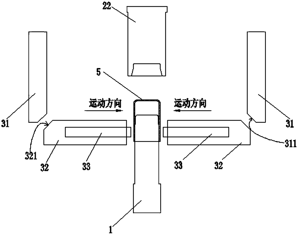
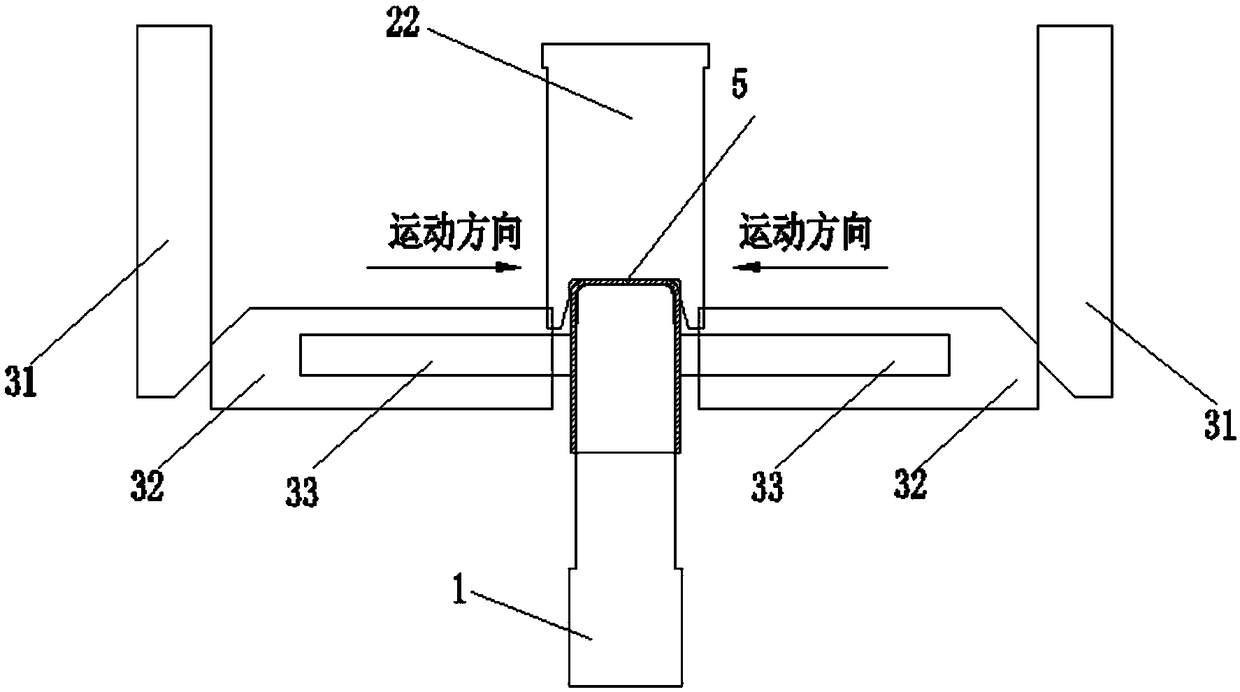
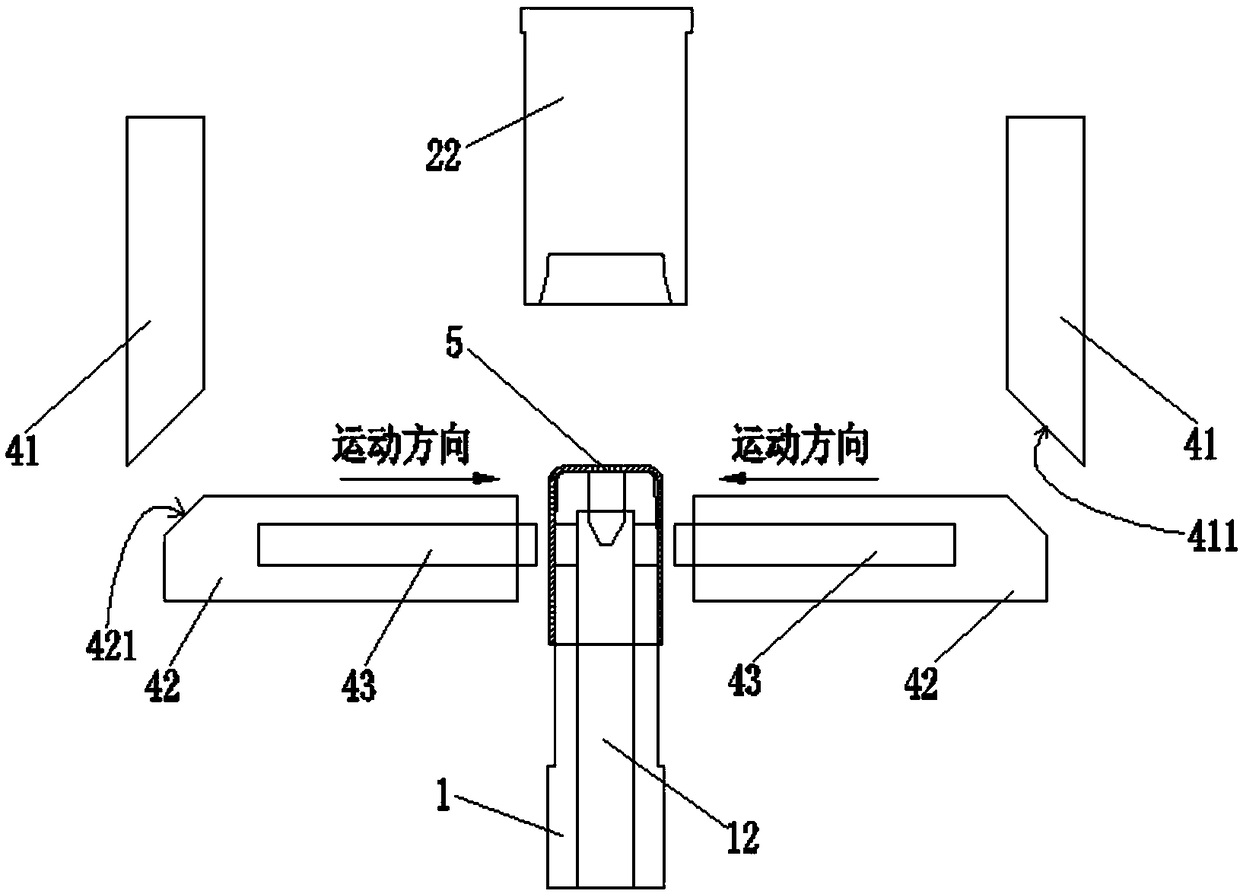
[0053] Such as Figure 1 to Figure 8 As shown, a side-punching balance mechanism for vehicle-mounted power supply casing parts includes a lower die base 1 , a lower die base balance locking mechanism 3 and a side punching mechanism 4 .
[0054] The lower mold base 1 is used to cover the housing parts 5 on the lower mold base 1 , and the side of the lower mold base 1 is provided with a stamping recess 11 .
[0055] The lower mold base balance locking mechanism 3 is used to fix the lower mold base 1;
[0056] The side punching mechanism 4 is used for side punching the shell parts 5 pressed on the lower mold base 1 .
[0057] The side punching balance mechanism of the present invention adds a lower mold base balance locking mechanism 3, and the lower mold base 1 is fixed by the lower mold base balance locking mechanism 3. When the side punching mechanism 4 performs side punching on the shell parts 5 , It can ensure that the lower die base does not shift, shake, or skew after be...
Embodiment 2
[0083] The difference between this embodiment 2 and embodiment 1 lies in the specific structure of the balance locking mechanism of the lower mold base, and the special anti-blocking mechanism for waste materials has been cancelled.
[0084] In this embodiment 2, aiming at the case that there is a central hole at the bottom or the top of the casing parts, this embodiment 2 provides another specific structure of the balance locking mechanism of the lower mold base. Such as Figure 9 , Figure 10 As shown, the balance locking mechanism of the lower mold base includes an upper mold, a positioning pin 35 and a guide pin hole 36 arranged on the lower mold base 1 and arranged along the central axis of the lower mold base. The positioning pin 35 is fixed on the upper mold base by a fixed block 34 On the mold, driven by the upper mold to move up and down, the positioning pin 35 is used to move downwards under the drive of the upper mold and penetrates in the guide pin hole 36, wherei...
Embodiment 3
[0090] On the basis of the side impact balance mechanism of the automobile on-board power supply casing parts of embodiment 1, such as Figure 11 to Figure 13 As shown, a side punching method for shell parts includes the following steps:
[0091] Step S1, putting the shell parts 5 on the lower mold base 1;
[0092] Step S2, using the lower mold base balance locking mechanism 3 to fix the lower mold base 1; the lower mold base balance locking mechanism 3 includes an upper mold, a first wedge 31, a first slider 32 and a clamping block 33;
[0093] Step S3, using the side punching mechanism 4 to carry out side punching on the shell parts 5 pressed on the lower die base 1, the side punching mechanism 4 includes an upper die, a second wedge 41, and a second slider 42 And the punch 43, the second oblique wedge 41 and the first oblique wedge 31 have a common upper mold.
[0094] After the step S1, a step T1 is also included, using the pushing and unloading mechanism 2 to press the ...
PUM
 Abstract
Description
Claims
Application Information
 - R&D
- Intellectual Property
- Life Sciences
- Materials
- Tech Scout
- Unparalleled Data Quality
- Higher Quality Content
- 60% Fewer Hallucinations
Browse by: Latest US Patents, China's latest patents, Technical Efficacy Thesaurus, Application Domain, Technology Topic, Popular Technical Reports.
© 2025 PatSnap. All rights reserved.Legal|Privacy policy|Modern Slavery Act Transparency Statement|Sitemap|About US| Contact US: help@patsnap.com


