Laser welding clamp for copper bar connecting piece of battery module

A technology for laser welding fixtures and battery modules, applied in laser welding equipment, welding equipment, manufacturing tools, etc., can solve problems affecting battery module performance, safety issues, loose connections, etc., to achieve easy replacement, easy operation, and guaranteed Effect of Mounting Accuracy

Active Publication Date: 2021-10-22
东莞市万连实业有限公司
View PDF13 Cites 4 Cited by
  • Summary
  • Abstract
  • Description
  • Claims
  • Application Information

AI Technical Summary

Problems solved by technology

In the traditional connection process, the PIN can be screwed on the copper bar or riveted on the copper bar, but these connection methods have the following disadvantages: after the PIN is connected to the copper bar, it is only surface contact, and there will be a certain gap. It will expand and shrink when it is cold. It may be because the expansion and contraction coefficients are not exactly the same, which will eventually cause the connection between the male head and the copper bar to loosen. When the current is passed, the temperature will rise higher, which will seriously affect the performance of the battery module and even cause safety question
In order to solve this problem, the PIN can be connected to the copper bar by laser welding, but there is currently no fixture on the market that can assist the laser welding of the copper bar connector.

Method used


Image

  • Laser welding clamp for copper bar connecting piece of battery module
  • Laser welding clamp for copper bar connecting piece of battery module
  • Laser welding clamp for copper bar connecting piece of battery module

Examples


Embodiment Construction

[0031] In order to make the purpose, technical solutions and advantages of the embodiments of the present invention clearer, the technical solutions in the embodiments of the present invention will be clearly and completely described below in conjunction with the drawings in the embodiments of the present invention. Obviously, the described embodiments It is a part of embodiments of the present invention, but not all embodiments. Based on the embodiments of the present invention, all other embodiments obtained by persons of ordinary skill in the art without creative efforts fall within the protection scope of the present invention.

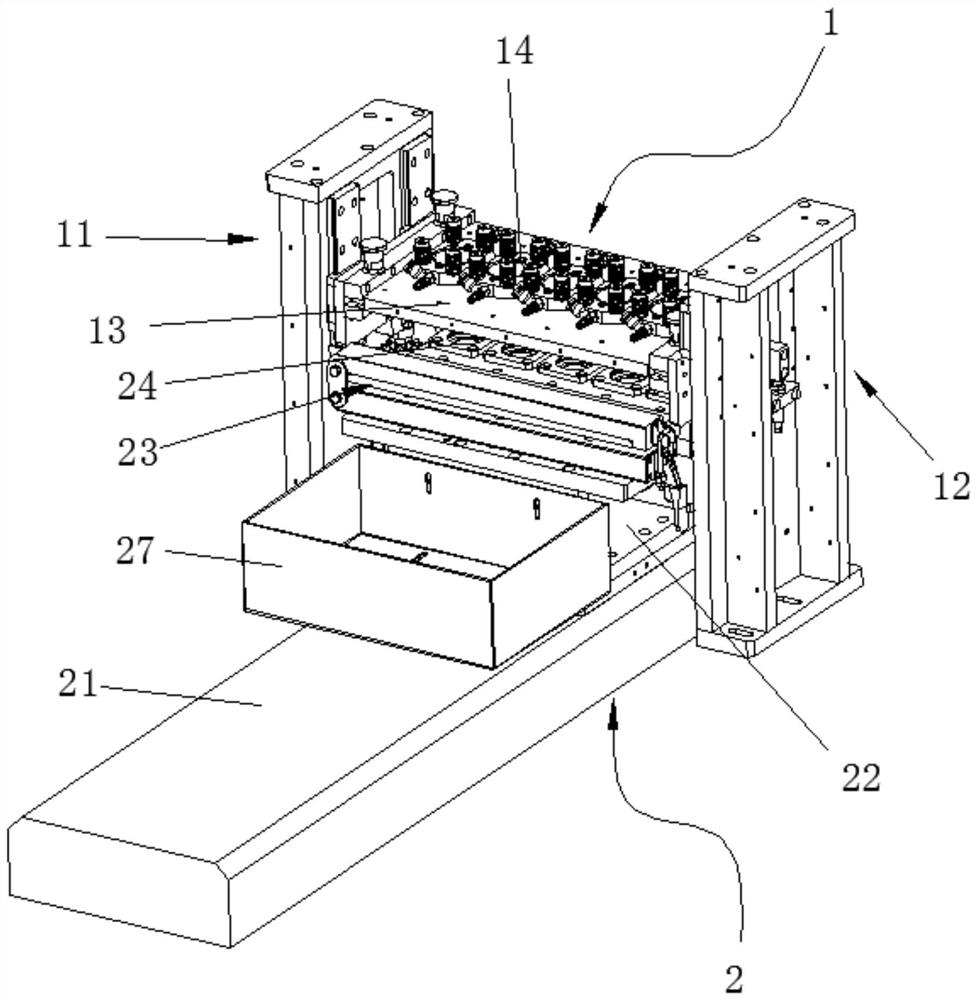
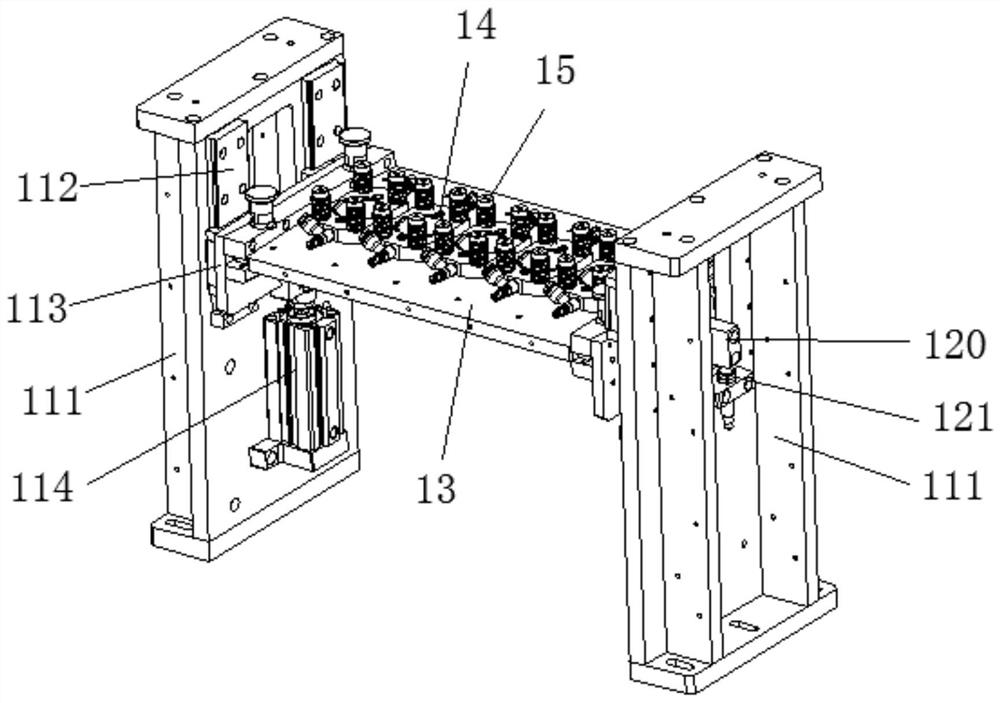
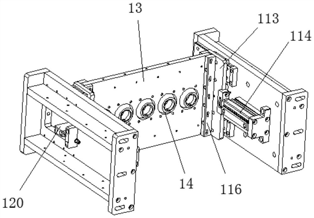
[0032] Please refer to figure 1 , an embodiment of the present invention provides a laser welding jig for battery module copper bar connectors, including a flexible pressing material positioning mechanism 1 and used for positioning the battery module copper bar connecting parts and transferring them to the flexible pressing material The product p...


PUM


Abstract

The invention discloses a laser welding clamp for a copper bar connecting piece of a battery module. The laser welding clamp comprises a flexible material pressing and positioning mechanism and a product positioning and feeding mechanism, wherein the flexible material pressing and positioning mechanism comprises a first lifting driving device, a second lifting driving device, a pressing head mounting plate and pressing heads, and the pressing heads are movably arranged on the pressing head mounting plate through elastic connecting pieces; the product positioning and feeding mechanism comprises a feeding translation device, a clamp base, a product fixing clamp and positioning sleeves; and the feeding translation device can drive all the positioning sleeves to move to the positions under the corresponding pressing heads. The positions of a copper bar and a PIN can be ensured not to deviate, the mounting precision of the copper bar and the PIN can be ensured, so that the laser welding clamp assists a laser generating mechanism to carry out laser welding on the copper bar and the PIN. The pressing heads are flexibly arranged and cannot crush the copper bar. The clamp can be compatible with different products, the corresponding positioning sleeve and the corresponding pressing head can be replaced according to the size and the length of the PIN, and replacement is convenient. In addition, a protective gas runner can be arranged in each pressing head.

Description

technical field [0001] The invention relates to the technical field of welding equipment for battery connectors, and more specifically, relates to a laser welding fixture for battery module copper bar connectors. Background technique [0002] In the connection mode of the battery module, the battery module can be connected to another battery module through the cooperation of the copper bar connector with the male PIN and the copper bar connector with the female PIN. In the traditional connection process, the PIN can be screwed on the copper bar or riveted on the copper bar, but these connection methods have the following disadvantages: after the PIN is connected to the copper bar, it is only surface contact, and there will be a certain gap. It will expand and shrink when it is cold. It may be because the expansion and contraction coefficients are not exactly the same, which will eventually cause the connection between the male head and the copper bar to loosen. When the curr...

Claims


Application Information

Patent Timeline
Patent Type & Authority Applications(China)
IPC IPC(8): B23K26/21B23K26/70
CPCB23K26/21B23K26/702Y02E60/10
Inventor 谢仁锋谢林江刘贻安
Owner 东莞市万连实业有限公司
Why Eureka
Try Eureka