
Automatic cloth spreading visual-positioning embroidery equipment

A visual positioning and embroidery technology, which is applied in the field of towel embroidery, can solve problems such as difficulty in ensuring embroidery continuity and affecting work efficiency, and achieve the effects of omitting manual cloth changes, increasing automation, and improving embroidery quality

Pending Publication Date: 2019-12-31
赵海
View PDF16 Cites 3 Cited by
  • Summary
  • Abstract
  • Description
  • Claims
  • Application Information

AI Technical Summary

Problems solved by technology

[0003] In the above scheme, the whole piece of cloth can be automatically fed and embroidered, but in the above scheme, after the front piece of cloth is embroidered, the rear end of the cloth enters the embroidery frame, and it needs to be repositioned manually according to the embroidery position of the front piece of cloth before continuing to embroider the rear section operation, it is difficult to ensure the continuity of embroidery, which affects work efficiency

Method used

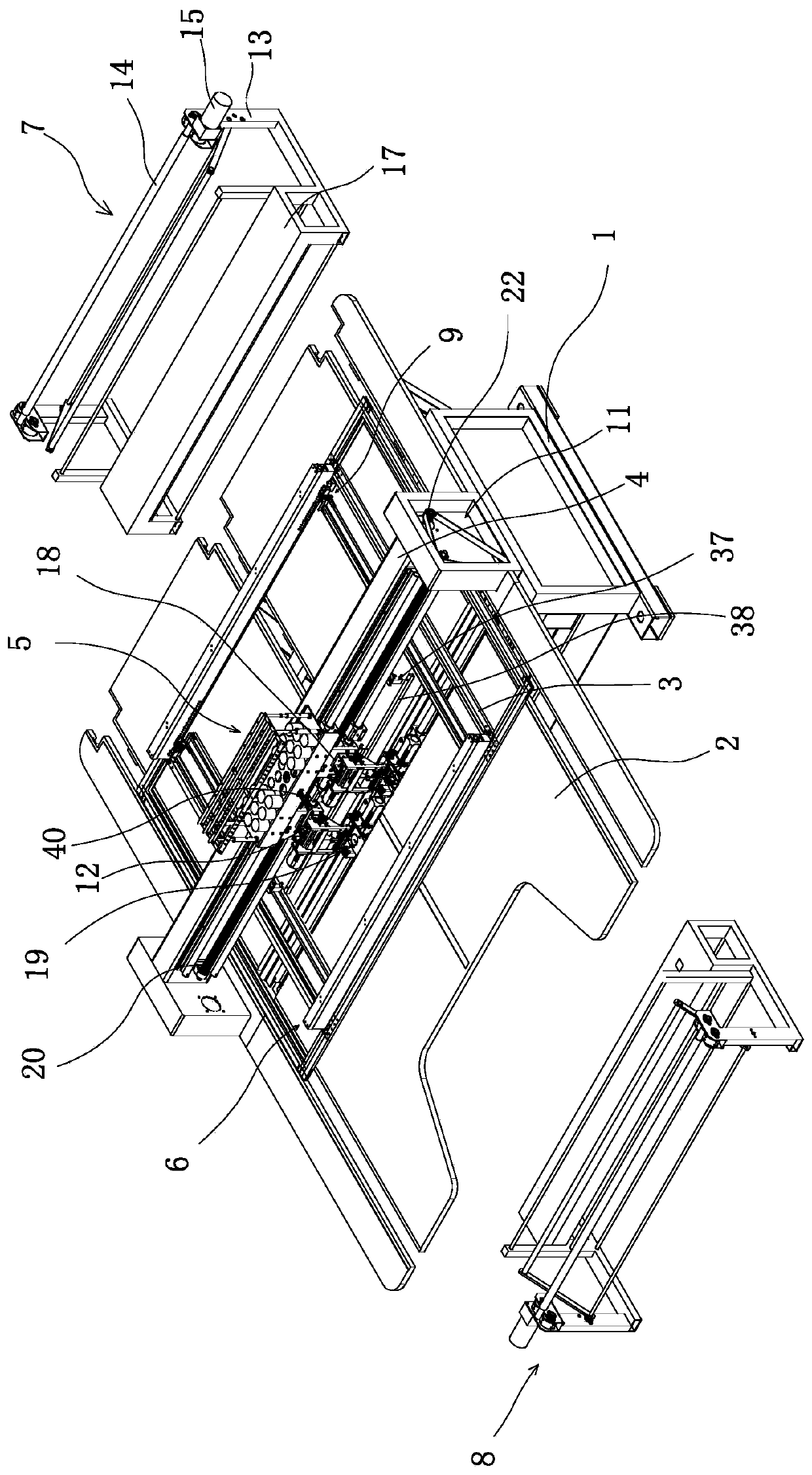
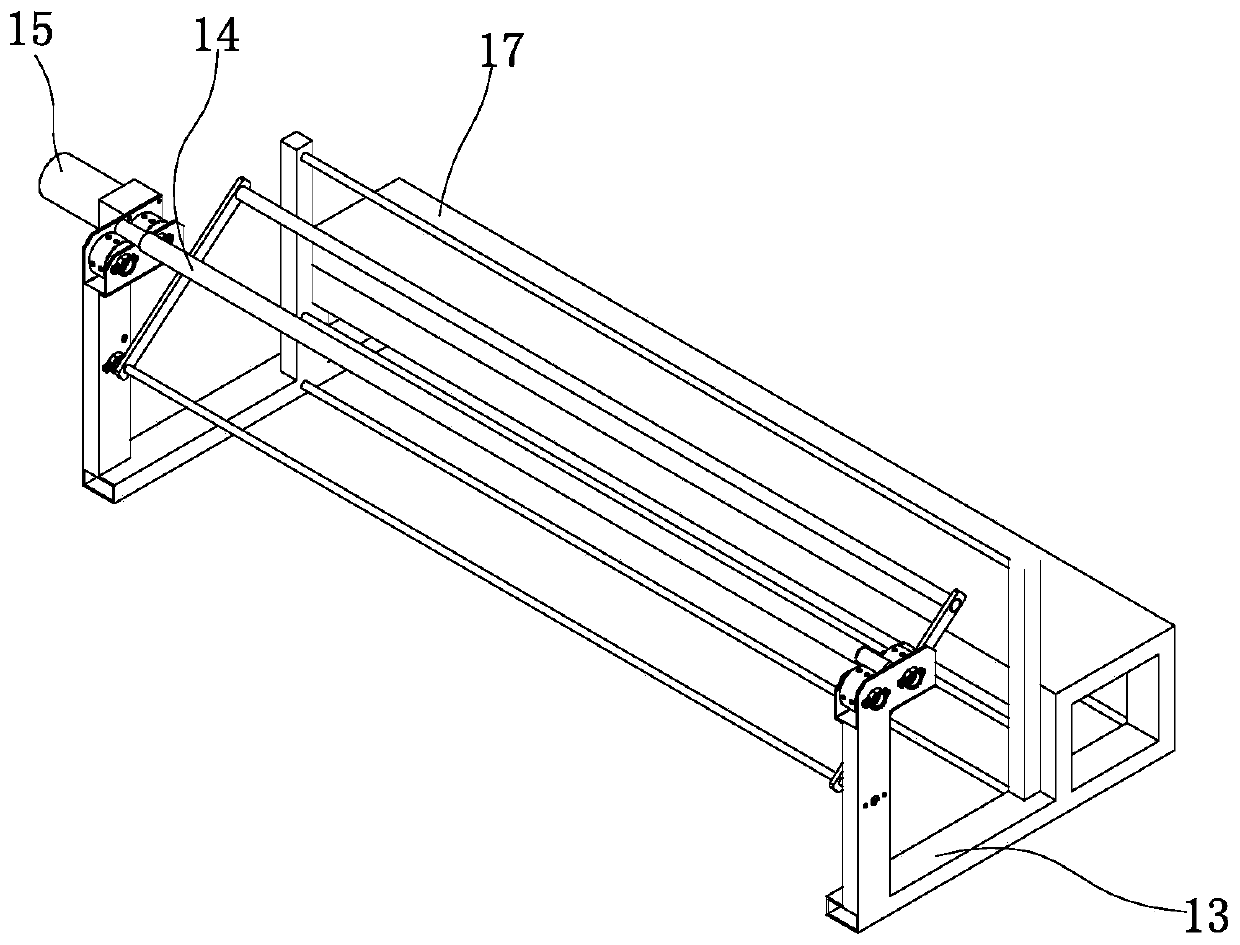
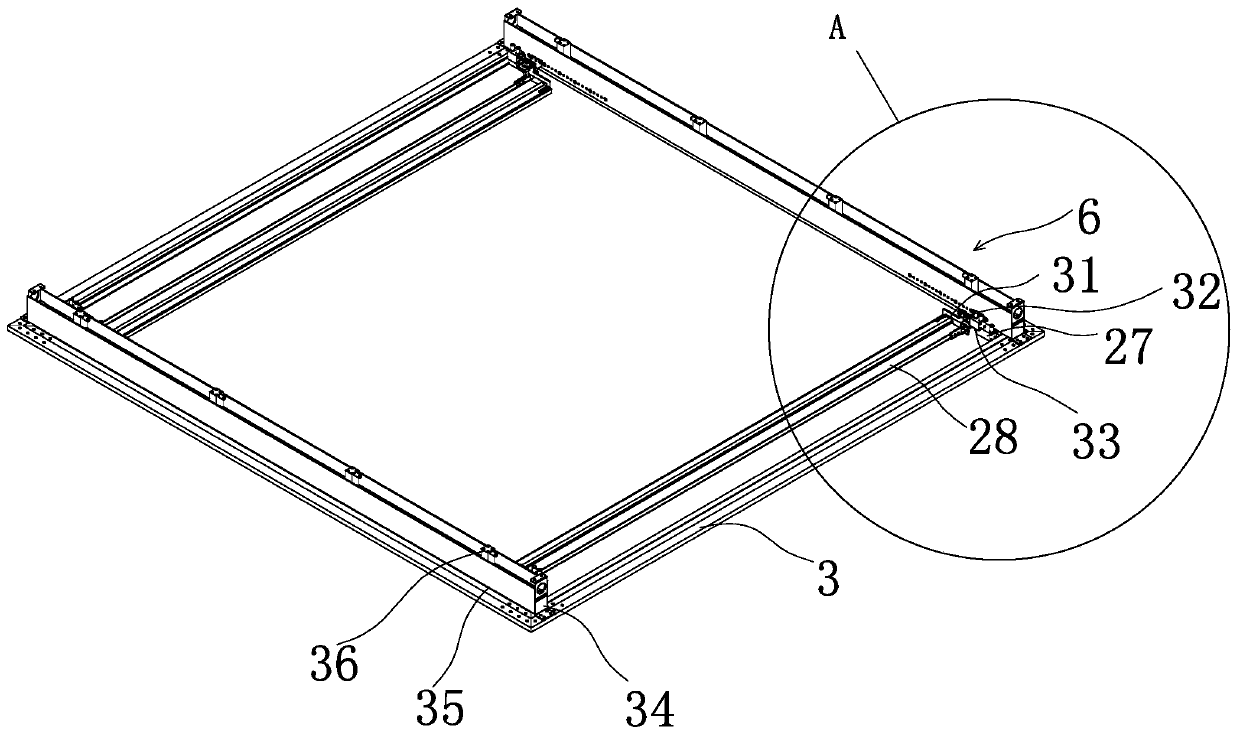

Image

  • Automatic cloth spreading visual-positioning embroidery equipment
  • Automatic cloth spreading visual-positioning embroidery equipment
  • Automatic cloth spreading visual-positioning embroidery equipment

Examples


Embodiment 2

[0049] The basic principle of the second embodiment is basically the same as that of the first embodiment, except that the embroidery frame 3 is transmission-connected with at least one group of embroidery frame driving components that drive the embroidery frame 3 in a direction perpendicular to the beam 4 . Embroidery assembly 5 transmission connection and drive embroidery assembly 5 move along the head drive assembly 11 of beam 4 direction, embroidery assembly 5 includes head assembly 18 and shuttle box assembly 19, and described head drive assembly 11 includes the The first screw rod 20 in the assembly 18 and the second screw rod 21 passing through the shuttle box assembly 19, the first screw rod 20 and the second screw rod 21 are respectively parallel to the beam 4, and the head assembly 18 and the shuttle The box assembly 19 is connected to the first screw 20 and the second screw 21 through a nut driving connection, and the same end and the same side of any of the first sc...

Embodiment 3

[0052] The basic principle of the third embodiment is basically the same as that of the first embodiment, the difference is that the image collector 12 is fixedly arranged on the girder 4, and the image collector 12 is connected to the girder 4 or the embroidery assembly 5 through the bracket seat 40 superior. The bracket base 40 includes a base body 41 and a bracket 42 protruding from the base body 41, the image collector 12 is arranged at the end of the bracket 42 away from the base body, and the base body 41 is slidably connected to the girder 4 . A first guide mechanism is provided on the seat body 41, a second guide mechanism is provided on the embroidery assembly 5 or the beam 4, the first guide mechanism and the second guide mechanism cooperate, and the seat The body 41 is connected with a linear driver that drives the seat body 41 to move linearly along the second guide mechanism.

[0053] The linear driver pushes the seat body 41 to move horizontally along the girde...


PUM


Abstract

The invention belongs to the field of embroidery equipment and provides automatic cloth spreading visual-positioning embroidery equipment. The equipment comprises a frame, an embroidery frame is arranged on a countertop of the frame, a crossbeam of the frame is provided with an embroidery component, the embroidery frame is provided with a cloth clamping component, and a first cloth rolling mechanism and a second cloth rolling mechanism are arranged on two sides, perpendicular to the crossbeam, of the frame respectively. At least one image collector is arranged on the crossbeam or the embroidery component. Cloth entering the embroidery frame is shot through the image collector, the cloth position and embroidery positions on the cloth are determined after image processing, a needling originis provided for an embroidery mechanism, continuous embroidery is realized while needle alignment is avoided, and embroidery efficiency is improved.

Description

technical field [0001] The invention belongs to the field of towel embroidery machines, and relates to an automatic auxiliary cloth visual positioning embroidery device. Background technique [0002] The embroidery machine has fast embroidery speed and high efficiency, but due to the limitation of the size of the embroidery frame, large-scale fabrics cannot be clamped on the embroidery frame at one time to complete the embroidery, such as curtains, wall coverings, etc. During the embroidery process of small-scale embroidery, the operator needs to stop the machine to take the cloth after each embroidery and re-clamp the cloth to be embroidered into the embroidery frame. During the embroidery process of the first mate embroidery, after embroidering a region, the operator needs to loosen the cloth clamp to readjust the cloth position and lock it again. If you adjust the position of the fabric or change the fabric midway, you need to re-align the flower. In the prior art, need...

Claims


Application Information

Patent Timeline
Patent Type & Authority Applications(China)
IPC IPC(8): D05C9/06D05C9/16G01B11/00
CPCD05C9/06D05C9/16G01B11/00
Inventor 周伟俞凯王亮曹万里王立庆
Owner 赵海
Learn More