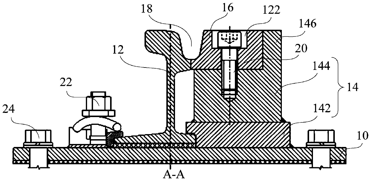
Turnout mechanism and rail system
A technology for turnouts and guard rails, which is applied in the directions of tracks, track superstructures, roads, etc., can solve the problems that the operation status of the turnout mechanism cannot be guaranteed, increase the maintenance cost and difficulty of maintenance, and the guard rails cannot be replaced or adjusted, and reduce maintenance. Cost and maintenance difficulty, the effect of reducing maintenance difficulty and assembly processing difficulty
- Summary
- Abstract
- Description
- Claims
- Application Information
AI Technical Summary
Problems solved by technology
Method used
Image
Examples
Embodiment 1
[0043] Such as figure 1 As shown, the first embodiment of the present invention proposes a turnout mechanism 1 , including: a basic rail 12 , a mounting part 14 and a guard rail 16 .
[0044] Specifically, such as figure 2As shown, the basic rail 12 and the mounting part 14 are all arranged on the backing plate 10, the guard rail 16 is arranged on the mounting part 14, one side of the guard rail 16 is attached to the basic rail 12, and the guard rail 16 and the basic rail 12 are in common Constituted track groove 18, guarantees tram to advance.
[0045] Wherein, the installation part 14 installs the guard rail 16, avoids the casting installation method of the guard rail 16 in the related art, and can ensure the installation strength of the guard rail 16, and avoids the direct connection of the guard rail 16 and the basic rail 12 to the basic rail 12 in the related art. damage; the guard rail 16 and the mounting part 14 are detachably connected, and when the guard rail 16 we...
Embodiment 2
[0048] Such as figure 1 As shown, the second embodiment of the present invention provides a turnout mechanism 1 , including: a basic rail 12 , a mounting part 14 and a guard rail 16 , wherein the mounting part 14 includes a platform 142 and a base 144 .
[0049] Specifically, such as figure 2 As shown, the base plate 142 is arranged on the backing plate 10, and the base 144 is positioned above the base plate 142; figure 2 The position shown in the middle guard rail 16) and the contact portion 146. The guard rail 16 is arranged in the installation space, the top of the mounting part 14 is in contact with the bottom wall of the guard rail 16, and a supporting force is given to the guard rail 16 in the vertical direction; the contact portion 146 is in contact with the side wall of the guard rail 16 Fitting, a limit is given to the guard rail 16 in the horizontal direction.
[0050] Such as figure 2 As shown, the base 144 has an L-shaped structure as a whole, so that the in...
Embodiment 3
[0058] Such as figure 1 As shown, the third embodiment of the present invention proposes a track system (not shown in the figure), including the switch mechanism 1 of any of the above-mentioned technical solutions, therefore, based on all the beneficial effects of the above-mentioned switch mechanism 1, no Discuss them one by one.
[0059] Specifically, the track system is a track system for a tram, and the tram can run on the track system.
PUM
 Abstract
Description
Claims
Application Information
 - R&D
- Intellectual Property
- Life Sciences
- Materials
- Tech Scout
- Unparalleled Data Quality
- Higher Quality Content
- 60% Fewer Hallucinations
Browse by: Latest US Patents, China's latest patents, Technical Efficacy Thesaurus, Application Domain, Technology Topic, Popular Technical Reports.
© 2025 PatSnap. All rights reserved.Legal|Privacy policy|Modern Slavery Act Transparency Statement|Sitemap|About US| Contact US: help@patsnap.com


