High-strength joint construction device suitable for composite cavity components

A high-strength, cavity technology, applied in the direction of connecting components, shaft equipment, pins, etc., can solve problems such as lack of equipment, and achieve high tensile effects

Active Publication Date: 2019-12-31
SHANGHAI TUNNEL ENG CO LTD +1
View PDF5 Cites 0 Cited by
  • Summary
  • Abstract
  • Description
  • Claims
  • Application Information

AI Technical Summary

Problems solved by technology

[0007] In order to solve the problem that the joints of the existing composite material laminated lining (composite cavity) structure only consider convenient installation and smooth grouting without leakage, and do not have high tensile and bending strengths. High Strength Joint Construction Device for Composite Cavity Components

Method used


Image

  • High-strength joint construction device suitable for composite cavity components
  • High-strength joint construction device suitable for composite cavity components
  • High-strength joint construction device suitable for composite cavity components

Examples


Embodiment Construction

[0022] In order to solve the problem that the joint of the existing composite lining (composite cavity) structure only considers easy installation and smooth grouting and does not have high tensile and flexural strength, the present invention provides a suitable High-strength joint construction device for composite cavity members.

[0023] The high-strength joint construction device of the present invention suitable for composite cavity components will be further described below with reference to the accompanying drawings and specific embodiments. Those skilled in the art can easily understand other advantages and functions of the present invention from the content disclosed in this specification.

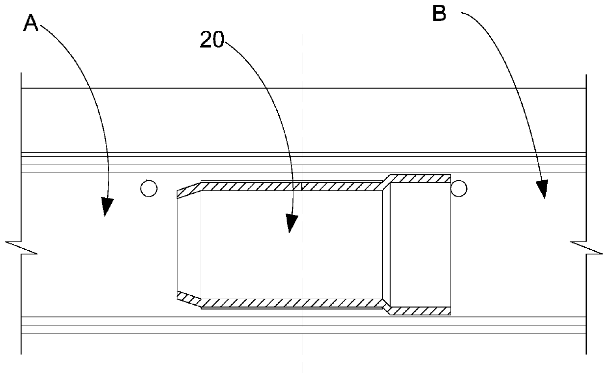
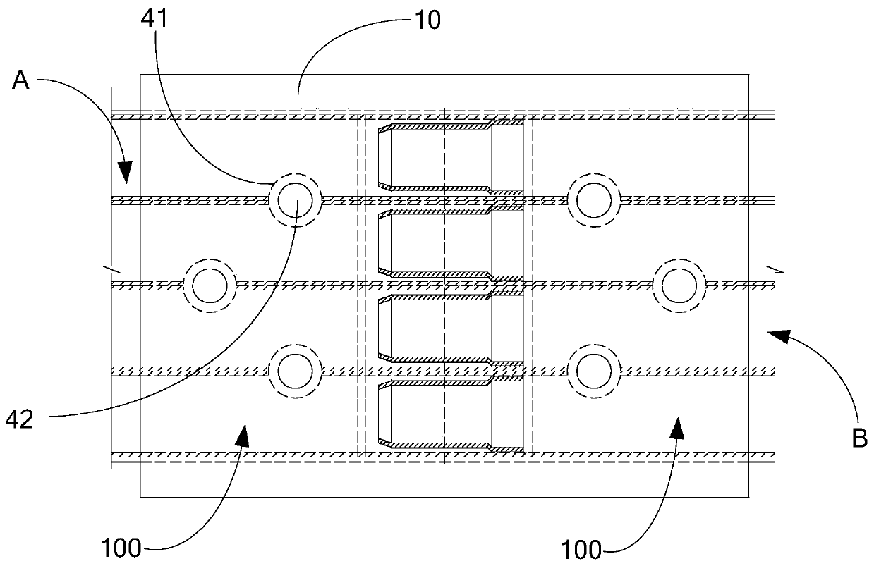
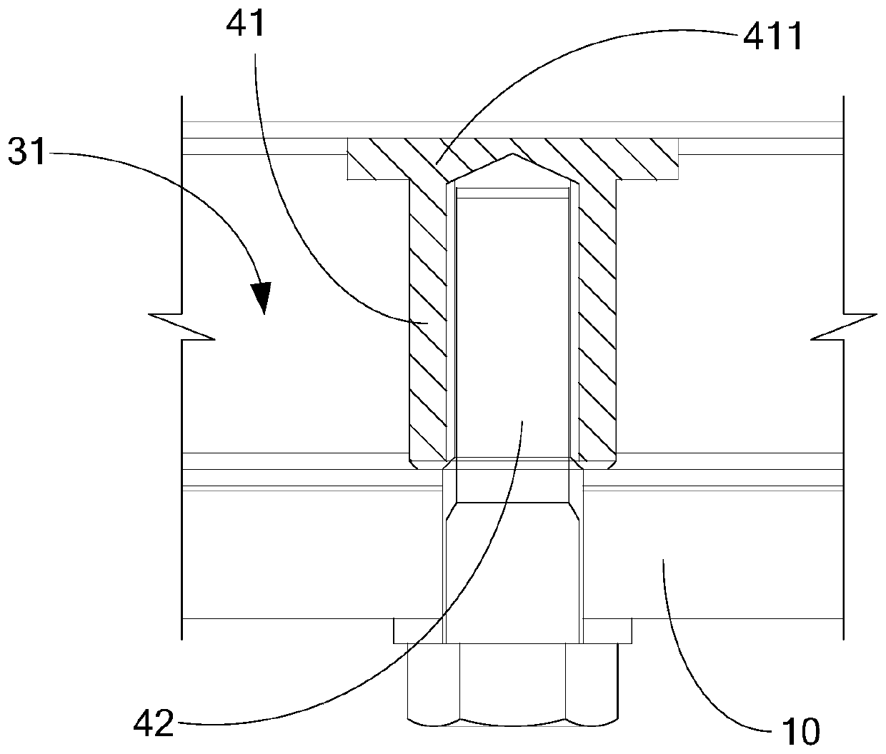
[0024] combine figure 2 and image 3 As shown, the present invention is suitable for a high-strength joint construction device of a composite cavity member, and is applied to a composite cavity member formed with a plurality of cavities 31, and a cavity wall 32 is provided betwe...


PUM


Abstract

The invention discloses a high-strength joint construction device suitable for composite cavity components. The high-strength joint construction device is applied to the composite cavity components where a plurality of cavities are formed. Cavity walls are arranged between adjacent cavities. The high-strength joint construction device comprises a high-strength connection plate arranged at the joint of the adjacent composite cavity components, a nut and a bolt. A connector assembly face located on the first side is formed on the two composite cavity components. The high-strength connection plates is attached and connected to the connector assembly face. Two connection parts are formed on the high-strength connection plate and are connected to the two composite cavity components correspondingly. The nut penetrates through the cavity walls from the second side of the composite cavity components to the first side. Connection holes are formed in the connection parts. The bolt penetrates through the connection holes and is in threaded connection with the nut. Specifically, the high-strength connection plate covers the joint between the adjacent composite cavity components, high-strengthconnection between the composite cavity components is achieved, the high-strength joint construction device has high tensile resistance and bending resistance, and a high-strength continuum is formedto effectively reinforce a stagger-jointed assembling tunnel.

Description

technical field [0001] The invention relates to the technical field of tunnel construction, in particular to a high-strength joint construction device suitable for composite cavity components. Background technique [0002] The shield method tunnel segment assembly tunnel construction technology has been widely used in subway, highway, drainage and other tunnel projects at home and abroad. However, the shield tunnel structure is composed of various tunnel segments assembled by bolts, and its stress structure presents a multi-hinge discontinuous circular arch structure, which relies heavily on the existence of lateral arch thrust. Accidental unloading, etc., will lead to large deformation of the structure, and the safety, reliability and durability of the structure will be seriously affected. It is urgent to strengthen the tunnel in time. Structural failure, resulting in accidents such as tunnel collapse. [0003] In order to get rid of this risk, it is an important and effe...

Claims


Application Information

Patent Timeline
Patent Type & Authority Applications(China)
IPC IPC(8): E21D11/04F16B13/10
CPCE21D11/04F16B13/04F16B13/10
Inventor 张学华万敏张衍陈宁威管攀峰赵玉同王普林王彩文李芹峰李迅
Owner SHANGHAI TUNNEL ENG CO LTD
Why Eureka
Try Eureka