Method, device and system for testing power consumption of subsystems in SOC system

A subsystem and power consumption technology, which is applied to measurement devices, electrical devices, and electrical power measurement. It can solve the problems of power consumption, difficulty, and excessive power consumption. Effect

Active Publication Date: 2022-01-28
MOLCHIP TECH (SHANGHAI) CO LTD
View PDF7 Cites 0 Cited by
  • Summary
  • Abstract
  • Description
  • Claims
  • Application Information

AI Technical Summary

Problems solved by technology

As an example, see figure 1 As shown, for example, the SOC system can usually include various functional subsystems such as ARM (Advanced RISC Machines), DSP (Digital Signal Processing), GPU (Graphics Processing Unit) and peripheral control modules. The entire SOC system Power and clock are often not independently provided to each subsystem. Usually, a DCDC (DC voltage to DC voltage) power supply supplies power to multiple subsystems of the system. For example, the ARM subsystem and the DSP subsystem use the same DCDC (DC voltage to DC voltage) power supply. DC voltage) power supply, the same PLL (phaselocked loop phase-locked loop) clock may be used by multiple subsystems and SOC internal bus at the same time, it is difficult to decompose the power consumption of each module
[0003] On the other hand, various subsystems are often still in a cooperative working state. For example, when the GPU encodes and decodes video data, the DSP is processing data algorithms, and the ARM is cooperating with routine operations. Multiple subsystems are involved in the work. At this time, the power consumption may exceed At this time, it is also necessary to analyze which subsystem the power consumption of the system is mainly consumed in.

Method used


Image

  • Method, device and system for testing power consumption of subsystems in SOC system
  • Method, device and system for testing power consumption of subsystems in SOC system
  • Method, device and system for testing power consumption of subsystems in SOC system

Examples


Embodiment

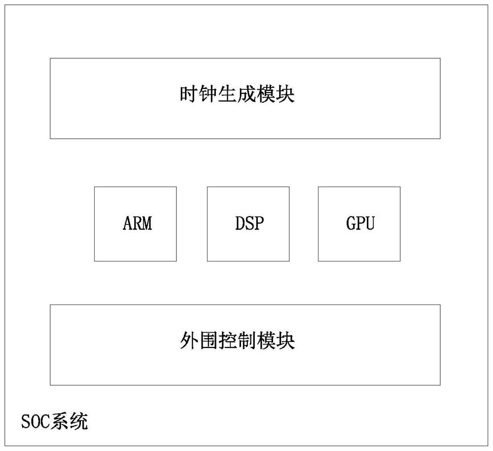
[0053] This embodiment provides a method for testing power consumption of subsystems in an SOC system.

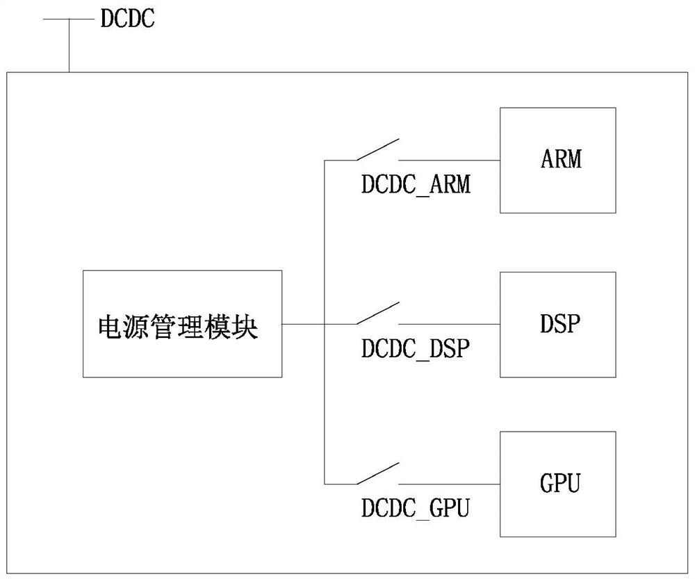
[0054] The SOC system includes multiple subsystems, and an independent DCDC power supply is set for each subsystem of the SOC system, and the DCDC power supply is correspondingly provided with a DCDC power switch. Each DCDC power switch is controlled to be turned on or off by a PMU (power management unit).

[0055] see figure 2 As shown, in this embodiment, the SOC system may include an ARM subsystem, a DSP subsystem, and a GPU subsystem. The aforementioned subsystems are sequentially provided with DCDC power supplies DCDC_ARM, DCDC_DSP, and DCDC_GPU. The DCDC_ARM controls the ARM subsystem. System power supply, DCDC_DSP control supplies power to the DSP subsystem, and DCDC_GPU controls supplies power to the GPU subsystem.

[0056] Compared with LDO (low dropout voltage regulator), the DCDC power supply has higher conversion efficiency and can handle large current.

[0...


PUM


Abstract

The invention discloses a method, a device and a system for testing power consumption of subsystems in an SOC system, and relates to the technical field of system chip testing. A method for testing the power consumption of subsystems in an SOC system, each subsystem is provided with an independent DCDC power supply, and the power management module controls the switch of the DCDC power supply to turn on or off, so that the target subsystem to be tested works under the DCDC power supply; and, An independent clock selection switch is set for each subsystem through the PLL control circuit, and the target subsystem to be tested works on the PLL clock by controlling the clock selection switch corresponding to each subsystem to be turned on or off. The invention can independently control the power supply and PLL clock of each subsystem, and control the output and shutdown of the power supply and PLL clock, so that the power consumption analysis of the subsystem becomes simple.

Description

technical field [0001] The invention relates to the technical field of system chip testing, in particular to a system power consumption testing method and application. Background technique [0002] At present, more and more embedded systems appear in daily life, especially the application of SOC (System On Chip). SOC chips are usually composed of many circuit modules or IP, including digital, analog, radio frequency and digital-analog hybrid circuits, etc., which have the characteristics of large scale, high integration, and small size. With the continuous evolution of SOC technology, the system performance is getting stronger and stronger, and the power consumption of the system is becoming more and more important. At present, system power consumption has become a key indicator to measure product competitiveness: the smaller the system power consumption, the longer the life, and the stronger the competitiveness. The power consumption of the system is mainly reflected in t...

Claims


Application Information

Patent Timeline
Patent Type & Authority Patents(China)
IPC IPC(8): G01R31/28G01R21/00G06F15/78
CPCG01R31/2851G01R21/00G06F15/7807Y02D10/00
Inventor 马全伟孙德印韦虎王奎秦建鑫张君宝
Owner MOLCHIP TECH (SHANGHAI) CO LTD
Why Eureka
Try Eureka