Backlight source, back plate thereof and manufacturing method

A manufacturing method and backlight technology, which are applied in optics, nonlinear optics, instruments, etc., can solve the problems of difficulty in realizing the backlight and complicated wiring layout on the backplane of the backlight, and achieve simplified wiring layout and high-contrast display. Effect

Active Publication Date: 2019-12-31
BOE TECH GRP CO LTD
View PDF7 Cites 5 Cited by
  • Summary
  • Abstract
  • Description
  • Claims
  • Application Information

AI Technical Summary

Problems solved by technology

However, when the number of LEDs increases, this solution will lead to complex wiring layout on the backplane of the backlight, and it is difficult to realize a backlight with a large number of LEDs.

Method used


Image

  • Backlight source, back plate thereof and manufacturing method
  • Backlight source, back plate thereof and manufacturing method
  • Backlight source, back plate thereof and manufacturing method

Examples


Embodiment Construction

[0040] In order to make the object, technical solution and advantages of the present invention clearer, the implementation manner of the present invention will be further described in detail below in conjunction with the accompanying drawings.

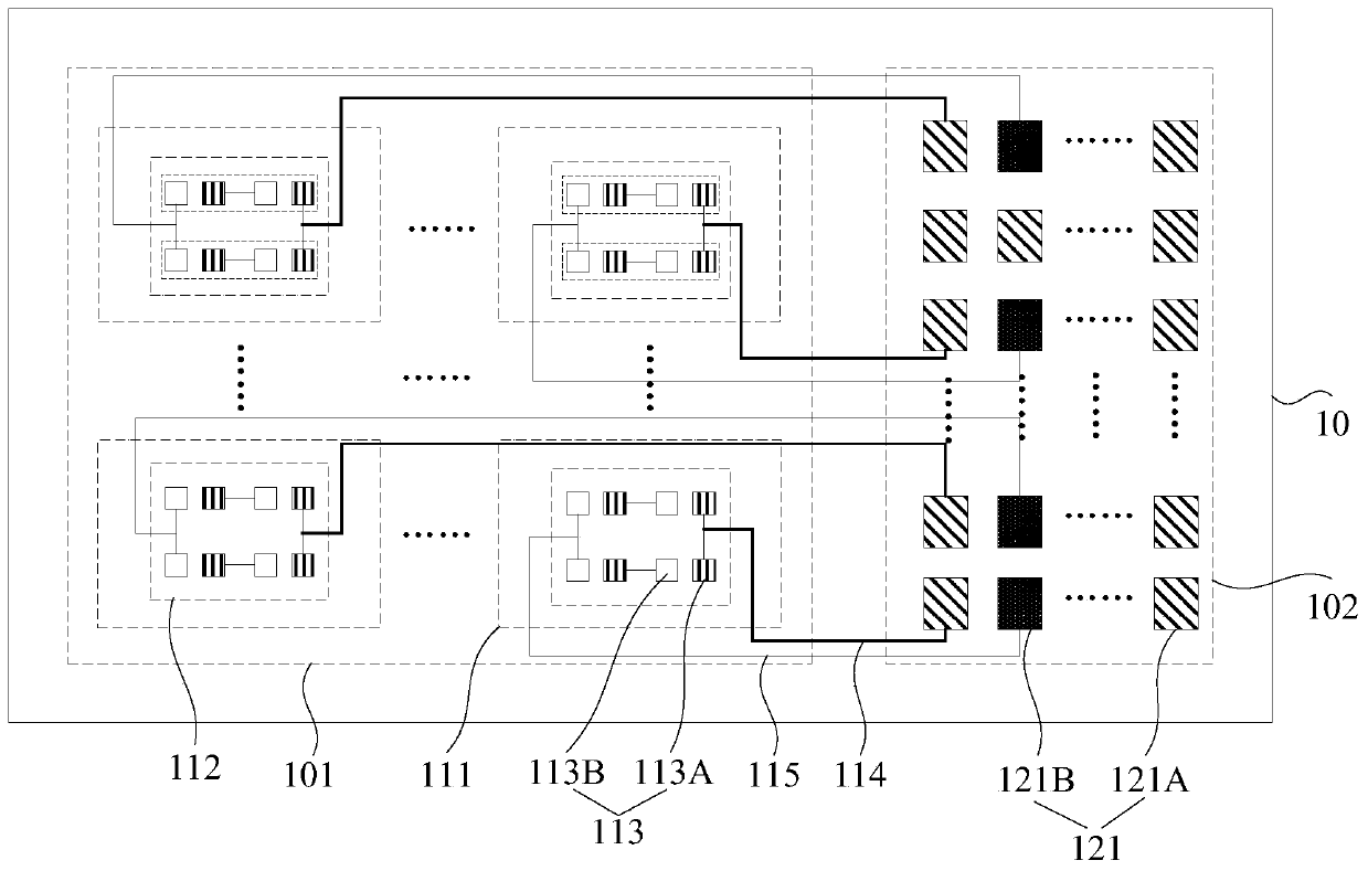
[0041] figure 1 It is a schematic structural diagram of a backlight backplane provided by an embodiment of the present invention. see figure 1 , the backlight backplane 10 has a light emitting area 101 and a binding area 102 located on the periphery of the light emitting area 101 .

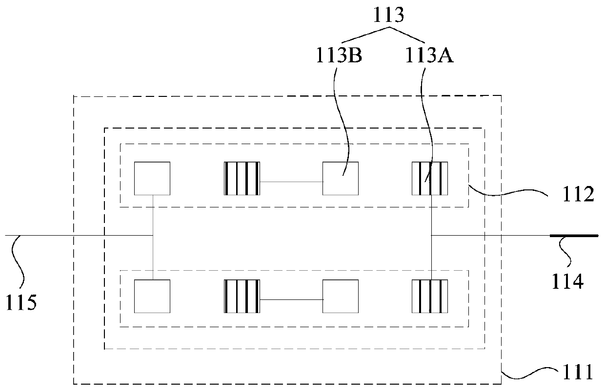
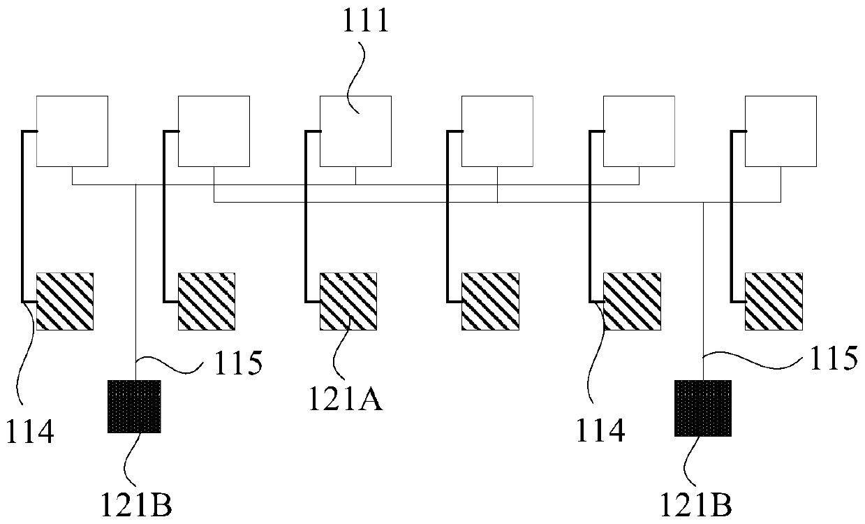
[0042] The light-emitting area 101 has a plurality of partitions 111, a group of LED pads 112 are arranged in each partition 111, a plurality of IC pads 121 are arranged in the bonding area 102, and a group of LED pads 112 includes at least two LED pads Pairs 113, each LED pad pair 113 includes an LED anode pad 113A and an LED cathode pad 113B. A group of LED pads 112 in each partition 111 is connected to the IC pads 121 in the binding area 102 through ...


PUM

PropertyMeasurementUnit
thicknessaaaaaaaaaa
widthaaaaaaaaaa
thicknessaaaaaaaaaa

Abstract

The invention discloses a backlight source, a back plate thereof and a manufacturing method, and belongs to the field of displays. The back plate of the backlight source is provided with a light-emitting area and a binding area, wherein the light-emitting area is provided with a plurality of subareas, a set of LED (Light Emitting Diode) bonding pads are arranged in each subarea, a plurality of ICbonding pads are arranged in the binding area; each set of LED bonding pads comprises at least two LED bonding pad pairs, each LED bonding pad pair comprises an LED anode bonding pad and an LED cathode bonding pad. The set of LED bonding pads in each subarea are connected with the IC bonding pads in the binding area through an anode wire and a cathode wire. High-contrast display of the backlight source can be realized by independently controlling each subarea. Each subarea is connected with the bonding area by only requiring one anode wire and one cathode wire, so that the wiring layout on theback plate of the backlight source can be simplified.

Description

technical field [0001] The invention relates to the field of displays, in particular to a backlight source, a backplane and a manufacturing method thereof. Background technique [0002] A liquid crystal display (English: Liquid Crystal Display, LCD for short) usually includes two parts: a backlight source and a display panel. Wherein, the backlight source can be a direct light-emitting diode (English: Light Emitting Diode, referred to as: LED) backlight source, and the backlight source can be controlled by zones (English: Area), which can meet the high contrast ratio (English: Contrast Ratio) of the liquid crystal display. Require. [0003] At present, the number of LEDs on the backlight source is small, and each LED in each partition can be connected to the driving circuit through wires. However, when the number of LEDs increases, this solution will lead to complicated wiring layout on the backplane of the backlight source, making it difficult to realize a backlight sourc...

Claims


Application Information

Patent Timeline
Patent Type & Authority Applications(China)
IPC IPC(8): G02F1/13357
CPCG02F1/133603G02F1/133612
Inventor 班圣光刘松
Owner BOE TECH GRP CO LTD
Why Eureka
Try Eureka