Optical fiber fusion splicer temperature control all-in-one machine

A technology of optical fiber fusion splicer and all-in-one machine, which is applied in temperature control, non-electric variable control, control/regulation system, etc. It can solve the problems of portable power generation equipment, large air gap, and low energy density.

Pending Publication Date: 2019-12-31
韩尊炳
View PDF0 Cites 0 Cited by
  • Summary
  • Abstract
  • Description
  • Claims
  • Application Information

AI Technical Summary

Problems solved by technology

[0003] (1) The heat preservation equipment cannot provide its own power supply. Once it is disconnected from the power supply and works in the field for a long time in severe cold conditions, there is no efficient temperature control device to ensure the internal temperature, which will eventually affect the working state of the fusion splicer
[0004] (2) Although the fixed thermal insulation cavity has high reliability, the size of the fusion splicer that can be placed is single, and there are few types and models; and when heating a small fusion splicer, the air gap is large, the thermal resistance is large, and the heating speed is slow
[0005] (3) The heating of carbon fiber resistance wire is contact heating, the heating time is about 30 minutes, and the heating speed in the incubator is relatively slow; and during the operation of carrying the incubator, the optical fiber fusion splicer is easy to contact the carbon fiber resistance wire, causing the fusion machine damaged, less secure
[0006] (4) In the working area with harsh environment and complex terrain, the portable power generation equipment cannot be carried due to the weight, which makes the fusion splicer and many auxiliary optical cable operation equipment unusable due to power supply.
[0007] (5) Portable battery packs connected to some incubators generally use ternary lithium batteries, which have poor low-temperature performance, small charge-discharge rate, low energy density, and short cycle life

Method used


Image

  • Optical fiber fusion splicer temperature control all-in-one machine
  • Optical fiber fusion splicer temperature control all-in-one machine
  • Optical fiber fusion splicer temperature control all-in-one machine

Examples


Embodiment Construction

[0054] The implementation mode of the present invention is illustrated by specific specific examples below, and those who are familiar with this technology can easily understand other advantages and effects of the present invention from the contents disclosed in this description. Obviously, the described embodiments are a part of the present invention. , but not all examples. Based on the embodiments of the present invention, all other embodiments obtained by persons of ordinary skill in the art without making creative efforts belong to the protection scope of the present invention.

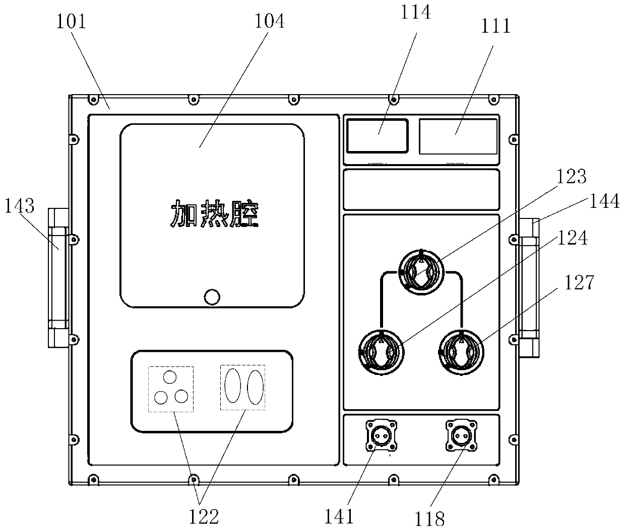
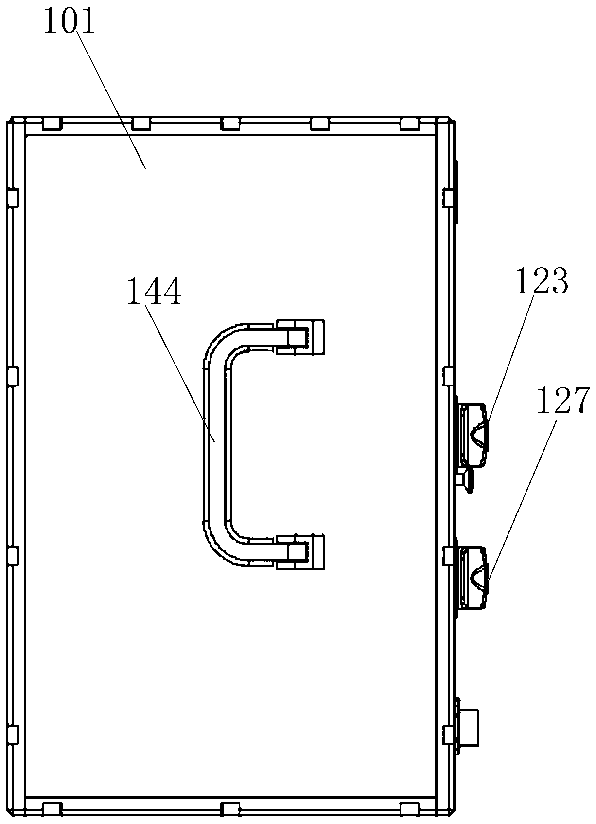
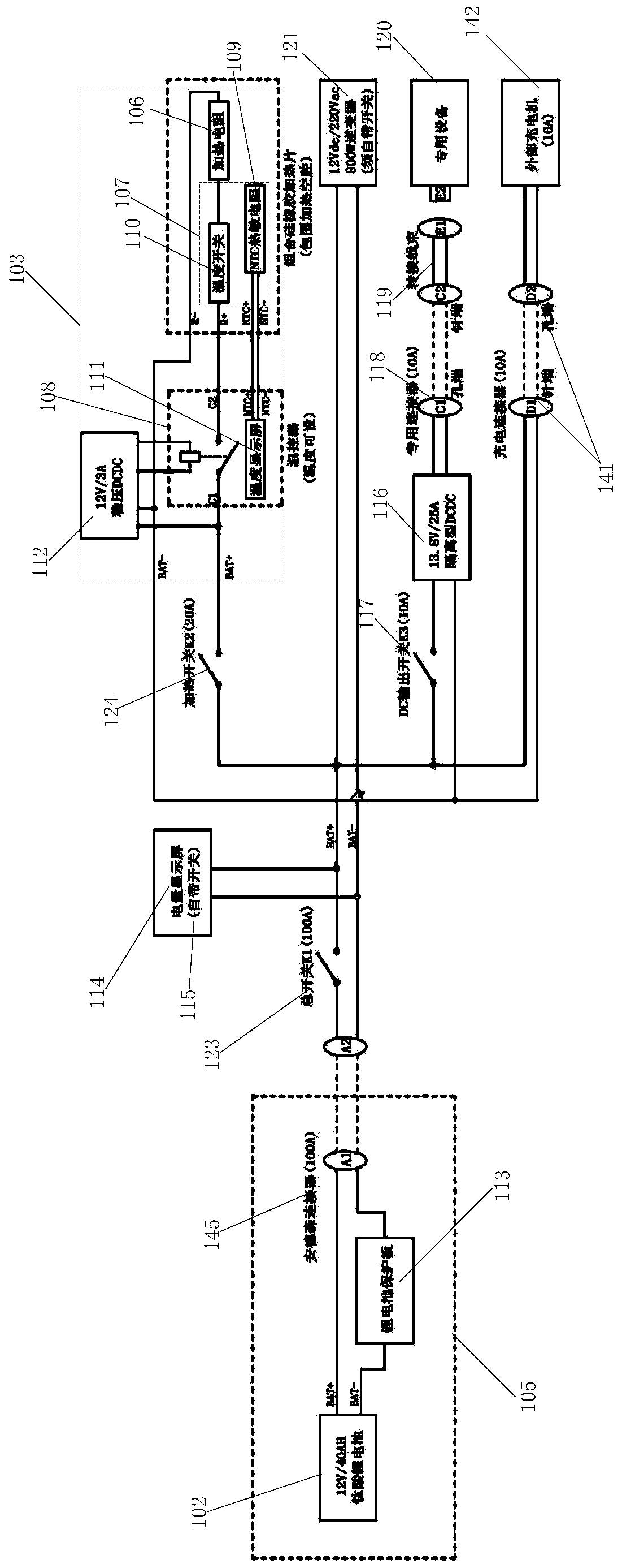
[0055] Please refer to figure 1 , figure 2 , image 3 , Figure 4 , figure 1A top view of an integrated temperature control machine for an optical fiber fusion splicer provided by an embodiment of the present invention; figure 2 for figure 1 A side view of a top view of an optical fiber fusion splicer temperature control integrated machine; image 3 An electrical schematic diagram of an ...


PUM


Abstract

The embodiment of the invention provides an optical fiber fusion splicer temperature control all-in-one machine, which comprises a box body, a rechargeable battery, a heating system and a heating cavity, wherein the heating cavity is arranged in the box body; the opening of the heating cavity is upward, and the heating cavity is used for accommodating an optical fiber fusion splicer; the heating system is used for heating the heating cavity; the rechargeable battery is used for supplying power to the heating system; the rechargeable battery is arranged in the battery box; and the battery box is fixed in the box body. Thus, the self rechargeable battery can be utilized to perform functions on the heating system, and the heating cavity can accommodate the optical fiber fusion splicer, so that the internal temperature is still ensured and the working state of the fusion splicer is ensured when the fusion splicer is separated from a power supply and works under long-time field severe coldconditions.

Description

technical field [0001] Embodiments of the present invention relate to the technical field of thermal insulation of fusion splicers, and in particular to an integrated temperature control machine for optical fiber fusion splicers. Background technique [0002] The existing thermal insulation equipment for fusion splicers in China is mainly an upper opening box, a fixed heating chamber, and an inner and outer double-layer structure. The inner layer is asbestos cloth, on which carbon fiber resistance wires are densely covered, and the outer layer is cold-proof cloth. The carbon fiber resistance wire is connected to the car battery or portable battery pack for heating, and the bottom is equipped with a DC fan to blow the warm air to the opening of the incubator. This type of insulation equipment has 5 disadvantages: [0003] (1) The heat preservation equipment cannot provide its own power supply. Once it is disconnected from the power supply and works in the field under severe...

Claims


Application Information

Patent Timeline
IPC IPC(8): G05D23/24
CPCG05D23/24
Inventor 韩尊炳丁宁夏甫根
Owner 韩尊炳
Why Eureka
Try Eureka