
Nail clippers with double cutting edges

A nail clipper and double-blade technology, which is applied in the field of nail clipper design, can solve the problems of high consumption cost of materials, low fault tolerance rate of nail clippers, scrapping of nail clippers, etc., and achieve simple structure, lower processing accuracy requirements, and lower production accuracy requirements Effect

Pending Publication Date: 2020-01-03
崔晃豪
View PDF0 Cites 2 Cited by
  • Summary
  • Abstract
  • Description
  • Claims
  • Application Information

AI Technical Summary

Problems solved by technology

At present, each family has at least one nail clipper, but the existing nail clippers only have the function of clipping on one side. When the blade of the nail clipper is damaged, the entire nail clipper will be scrapped, resulting in a loss of materials and user consumption costs. increased
Although in the prior art there has been described as an attached Image 6 The shown nail clippers have the function of clipping and cutting on both sides, which prolongs the service life of the nail clippers to a certain extent. When working, after the nail clipper blade on one side is closed, the nail clipper blade on the other side is also required to be closed in the same way, but This kind of nail clippers has very strict requirements on the distance between the blades on both sides. The resulting scrap rate is high, making it difficult to reduce the cost of the enterprise and improve economic benefits

Method used


Image

  • Nail clippers with double cutting edges
  • Nail clippers with double cutting edges
  • Nail clippers with double cutting edges

Examples


Embodiment Construction

[0024] The following will clearly and completely describe the technical solutions in the embodiments of the present invention with reference to the accompanying drawings in the embodiments of the present invention. Obviously, the described embodiments are only some, not all, embodiments of the present invention. Based on the embodiments of the present invention, all other embodiments obtained by persons of ordinary skill in the art without making creative efforts belong to the protection scope of the present invention.

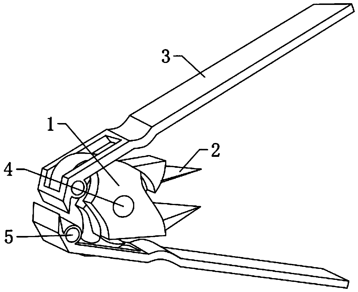
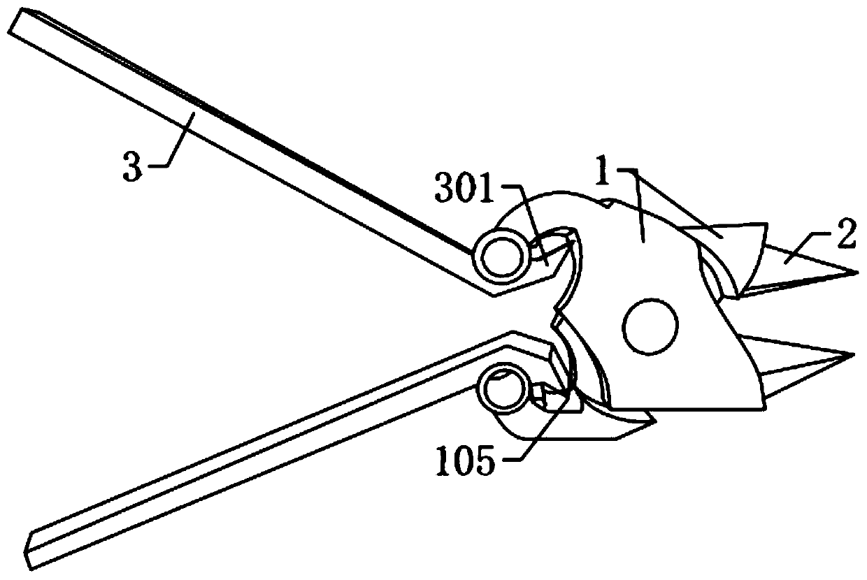
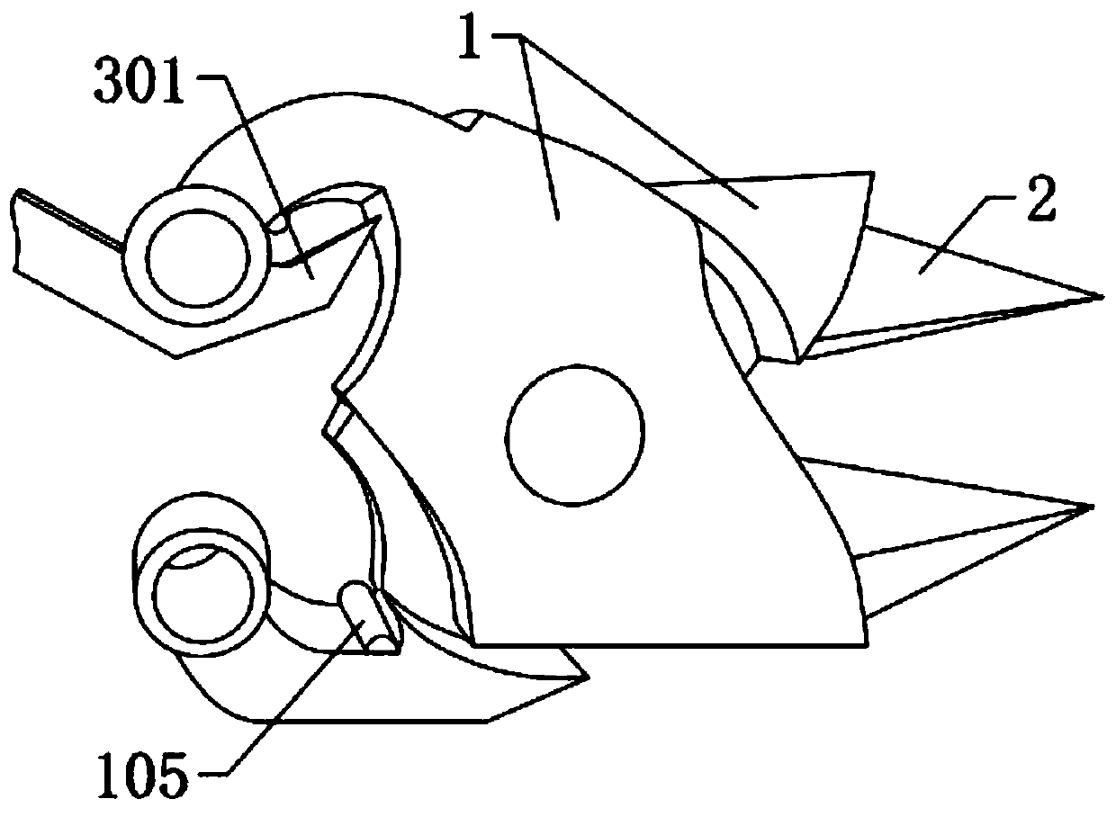
[0025] refer to Figure 1-4 , a double-edged nail clipper, a double-edged nail clipper, comprising two rotating parts 1 with the same structure, arranged symmetrically to each other and hinged to each other, the tail end of the rotating part 1 is fixedly equipped with a first cutting head 2, The front end positions of the two rotating parts 1 are hinged with a knife handle 3, and the knife handle 3 includes a second knife head 301 bent downward at the front en...


PUM


Abstract

The invention discloses nail clippers with double cutting edges. The nail clippers comprise two rotation parts which have the same structure, are symmetrically arranged, and are hinged, first cutter bits are fixedly mounted at the tail ends of the rotation parts, cutter handles are hinged to the front end positions of the two rotation parts, and the cutter handles comprise second cutter bits positioned at the front ends, bent downwards, and integrally formed; and when the two cutter handles rotate to be close to one sides of the first cutter bits, the distance between the two second cutter bits is smaller than the minimal distance between the two first cutter bits. The nail clippers with the double cutting edges are simple in structure, reasonable in design, and convenient to use, when thenail clippers work, after the cutter edges on one side are closed, the cutting edges on the other side are in the non-contact state, so that the problem that the cutting edges of the closed end can not contact is solved, the simultaneous closing of the cutting edges on two sides is not needed, therefore, the requirements for the production precision of the nail clippers is reduced, and the rejection rate is low; and in addition, under the condition that the cutting edges on one side are damaged and can not be used, the cutting edges on the other side can be utilized for realizing the clipping-trimming function of the nail clippers, so that the service life of the nail clippers is favorably prolonged.

Description

technical field [0001] The invention relates to the technical field of nail clipper design, in particular to a double-edged nail clipper. Background technique [0002] Nail clippers are an indispensable item in people's lives. With the development of society, various nail clippers have entered people's lives. There are more and more classifications of nail clippers, and the pertinence is becoming stronger and stronger. At present, each family has at least one nail clipper, but the existing nail clippers only have the function of clipping on one side. When the blade of the nail clipper is damaged, the entire nail clipper will be scrapped, resulting in a loss of materials and user consumption costs. increased. Although in the prior art there has been described as an attached Image 6 The shown nail clippers have the function of clipping and cutting on both sides, which prolongs the service life of the nail clippers to a certain extent. When working, after the nail clipper bla...

Claims


Application Information

Patent Timeline
Patent Type & Authority Applications(China)
IPC IPC(8): A45D29/02
CPCA45D29/02
Inventor 崔晃豪
Owner 崔晃豪
Learn More