Glass bending furnace

A hot bending furnace and glass technology, applied in glass production, glass molding, glass manufacturing equipment, etc., can solve the problems of large space occupied by hot bending furnaces, difficult production, difficult maintenance, etc., to facilitate later maintenance, The effect of fast heating speed and compact arrangement

Active Publication Date: 2022-06-03
北京多宾城建筑机械有限公司
View PDF11 Cites 0 Cited by
  • Summary
  • Abstract
  • Description
  • Claims
  • Application Information

AI Technical Summary

Problems solved by technology

[0003] The traditional bending furnace is a circular furnace, and the number of functional areas and bending molds of the bending furnace is proportional to its diameter. The larger the diameter of the bending furnace, the more functional areas and the number of bending molds, but the corresponding The more space it takes up; and the furnace bricks in the functional area of ​​the circular furnace are all fan-shaped, which is difficult to manufacture and difficult to maintain later.

Method used


Image

  • Glass bending furnace
  • Glass bending furnace
  • Glass bending furnace

Examples


Embodiment 1

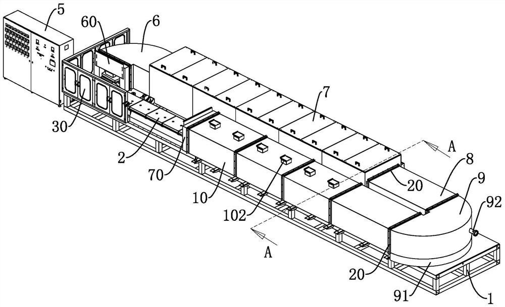
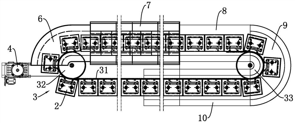
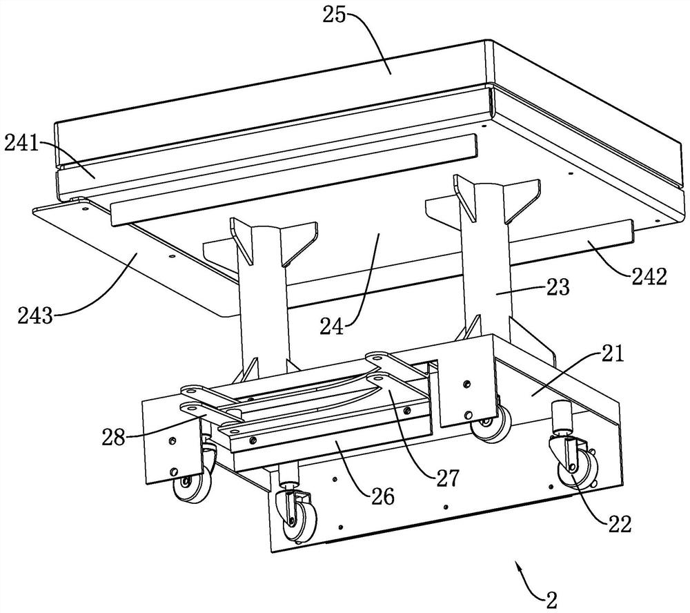
[0043] Embodiment 1: a kind of glass hot bending furnace, such as figure 1 , figure 2 As shown, it includes a rectangular frame 1 formed by welding a plurality of horizontally and vertically staggered square tubes. The upper end of the frame 1 slides and supports a material trolley 2, and the frame 1 is provided with a driving device 3 that drives the material trolley 2 to move. , the driving device 3 includes a chain guide rail 31 distributed in the shape of "back", the material trolley 2 is fixedly connected to the outer ring surface of the chain guide rail 31, and the frame 1 is provided with a power device 4 that drives the chain guide rail 31 to rotate. One side of 1 is also arranged with electric control box 5.

[0044] The upper end of the frame 1 is sequentially provided with a U-shaped feeding section 6, a thermal bending section 7, a first straight cooling section 8, a U-shaped discharging section 9 and a second straight cooling section 10 along the running directi...

Embodiment 2

[0071] Embodiment 2: The difference between this embodiment and Embodiment 1 is that the glass bending furnace of this embodiment is provided with a vacuum device 70 that provides negative pressure. It is difficult to meet the requirements of deep curvature. At this time, it is necessary to use external force (such as negative pressure adsorption) to assist natural collapse, so that the product meets the technical requirements.

[0072] The vacuum device 70 is arranged in the frame 1, directly below the running track 12 in the thermal bending section 7, as Figure 8 As shown, the vacuum device 70 includes a linear sub-rail 701 fixed on the bottom of the frame 1, a fixed seat 702 slidably mounted on the linear sub-rail 701, and an ejector cylinder 703 fixed on the fixed seat 702 with the output end distributed vertically upward. , the connecting seat 704 fixedly connected to the output end of the ejecting cylinder 703, the suction cup 705 installed on the upper end of the conne...


PUM


Abstract

The invention discloses a glass hot bending furnace, which comprises a frame, a material trolley slidably supported on the frame, a driving device for driving the material trolley to move, and a power device for providing power for the driving device. It is a closed circular flexible guide rail, which is rotatably installed on the frame, and the material trolley is connected with the flexible guide rail; the frame is provided with a hot bending furnace functional area along the running direction of the flexible guide rail. The glass bending furnace of the present invention changes the shape structure and operation mode, has more functional areas and mold bricks of the bending furnace under the same floor area, and effectively improves the glass bending efficiency.

Description

technical field [0001] The invention relates to the technical field of glass forming, in particular to a glass bending furnace. Background technique [0002] Hot bending furnace is a common equipment for hot bending and forming of automobile rearview mirror glass. At present, the commonly used hot bending furnace generally sets the heater at a fixed position above the turntable, and a plurality of hot bending molds are set on the periphery of the turntable, when the glass workpiece to be formed is placed on the hot bending mold and sent to the bottom of the heater , it is heated and formed by a heater. However, the existing hot bending furnaces often have the following obvious defects in their actual production and application process: [0003] The traditional bending furnace is a circular furnace, and the number of functional areas and bending molds of the bending furnace is proportional to its diameter. The larger the diameter of the bending furnace, the more functional ...

Claims


Application Information

Patent Timeline
Patent Type & Authority Patents(China)
IPC IPC(8): C03B23/025C03B23/035C03B35/14
CPCC03B23/025C03B23/0357C03B35/142Y02P40/57
Inventor 张然
Owner 北京多宾城建筑机械有限公司
Why Eureka
Try Eureka