Multifunctional detection vehicle
A vehicle detection, multi-functional technology, applied in the direction of roads, road repair, roads, etc., can solve the problems of insufficient functions and difficult to achieve detection, and achieve the effect of reducing shaking and avoiding falling.
- Summary
- Abstract
- Description
- Claims
- Application Information
AI Technical Summary
Problems solved by technology
Method used
Image
Examples
Embodiment 1
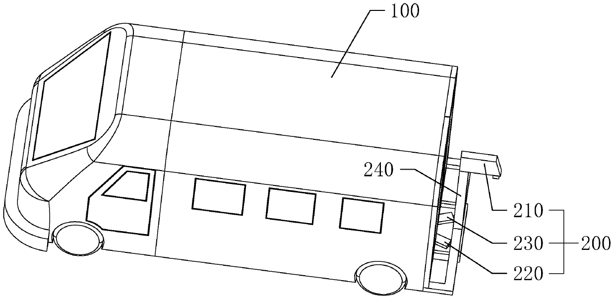
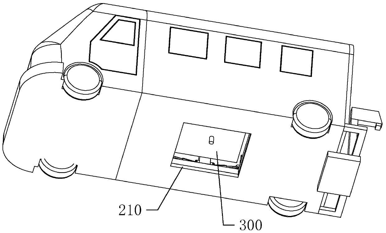
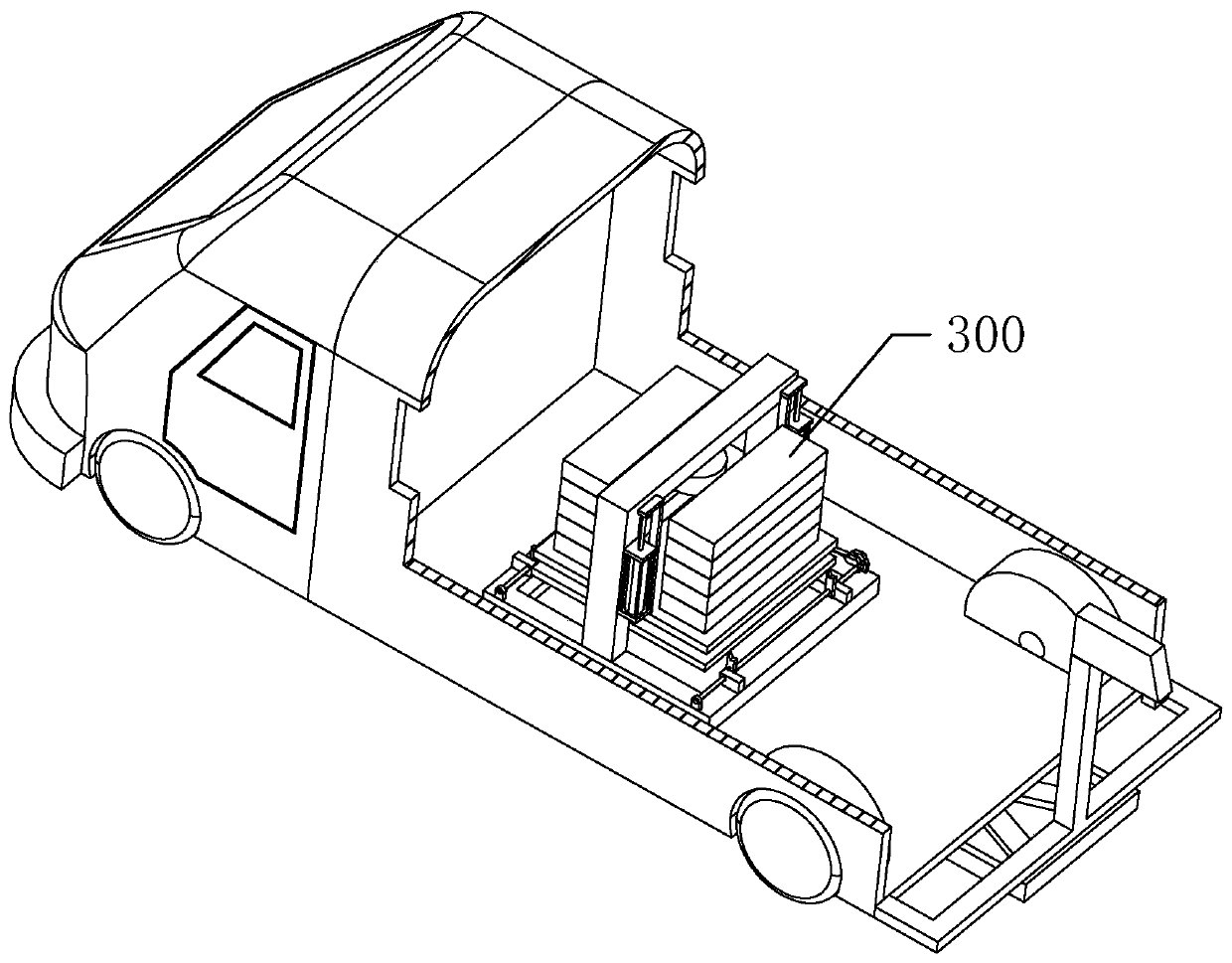
[0040] A multifunctional inspection vehicle, such as figure 1 As shown, including the vehicle body, 3D scanner and drop weight deflectometer.
[0041] The three-dimensional scanner is installed at the rear end of the vehicle body, which includes a CCD camera, a line laser emitter and an angle sensor. A mounting frame is fixedly installed at the rear end of the vehicle body, and the CCD camera is fixedly mounted on the mounting frame. Both the line laser emitter and the angle sensor are arranged on the chassis at the rear end of the vehicle body, and the line laser emitter and the angle sensor are arranged in a figure-eight shape. When in use, the line laser emitter projects a linear laser onto the road surface to be inspected, and the strip-shaped light strip is modulated by the three-dimensional information of the road surface and then imaged on the CCD camera to obtain data information of a longitudinal section, while the inspection vehicle During the driving process, with ...
Embodiment 2
[0055] refer to Figure 6 , The difference from Embodiment 1 is that four safety locks are fixedly installed on the frame, and are arranged in groups of two on both sides of the hammer drop device.
[0056] The safety lock includes a base, a connecting shaft, a support grip, a torsion spring and a support hydraulic cylinder, and the base is fixedly installed on the frame.
[0057] The connecting shaft is fixedly installed on the base, and the supporting gripper is connected to the rotating shaft so that it can rotate around the rotating shaft. There is a screw thread at the end of the rotating shaft, and a limit cover is threaded on the rotating shaft. Through a limit cover Axially limit the support gripper on the rotating shaft.
[0058] The torsion spring is sleeved on the connecting shaft, and a receiving groove is provided on the opposite side of the supporting handle and the base. One end of the torsion spring is inserted into the receiving groove on the supporting handl...
PUM
 Abstract
Description
Claims
Application Information
 - R&D
- Intellectual Property
- Life Sciences
- Materials
- Tech Scout
- Unparalleled Data Quality
- Higher Quality Content
- 60% Fewer Hallucinations
Browse by: Latest US Patents, China's latest patents, Technical Efficacy Thesaurus, Application Domain, Technology Topic, Popular Technical Reports.
© 2025 PatSnap. All rights reserved.Legal|Privacy policy|Modern Slavery Act Transparency Statement|Sitemap|About US| Contact US: help@patsnap.com


