
Movable track lifting device

A mobile and rail-based technology, which is applied in the field preparation of formwork/formwork/work frame, building components, construction, etc., can solve the problem of inability to apply variable cross-section high-rise bridge main towers, limited construction scope, and scope of application. narrow and other issues, to achieve the effect of simple installation and fixation, wide application range and improved safety

Pending Publication Date: 2020-01-03
CCCC WUHAN HARBOR ENG DESIGN & RES
View PDF0 Cites 0 Cited by
  • Summary
  • Abstract
  • Description
  • Claims
  • Application Information

AI Technical Summary

Problems solved by technology

This hoisting method is simple, but its scope of application is narrow. It can only climb vertically or obliquely along the building surface. It cannot be applied to the construction of high-rise buildings and bridge main towers with variable cross-sections, and the construction scope is limited.

Method used


Image

  • Movable track lifting device
  • Movable track lifting device
  • Movable track lifting device

Examples


Embodiment Construction

[0036] The present invention will be further described in detail below in conjunction with the accompanying drawings and specific embodiments.

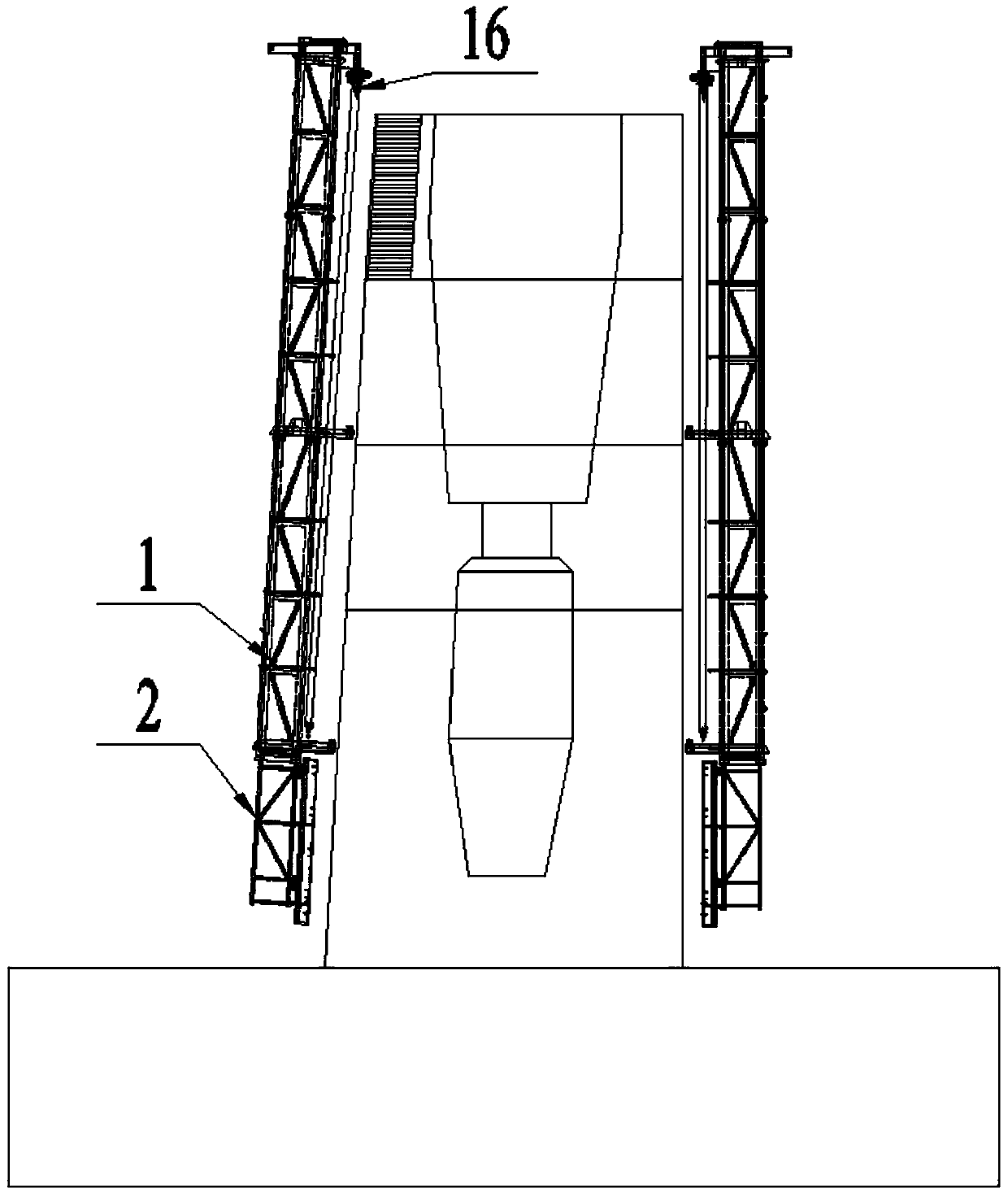
[0037] Such as Figure 1-10 , a movable track lifting device, the lifting device of this embodiment is used to lift the track unit 3, so that the track unit 3 can be reused repeatedly, reducing the cost of the track structure. The hoisting device of the present embodiment comprises a fixed truss 1 and a movable truss 2, such as figure 1 As shown, the fixed truss 1 of this embodiment is anchored on the finished concrete surface through embedded parts, and the movable truss 2 is a movable truss structure connected to the fixed truss 1 in a longitudinally movable manner.

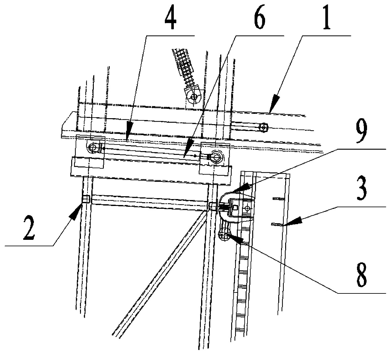
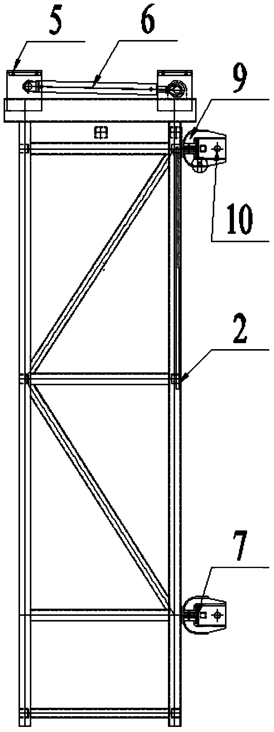
[0038] Such as figure 2 As shown, the lower end of the fixed truss 1 is provided with a longitudinal guide rail 4 extending in the longitudinal direction, the movable truss 2 is provided with a sliding shoe 5 slidingly connected to the longitudinal guide rail 4, and...


PUM


Abstract

The invention relates to the technical field of building construction structures, in particular to a movable track lifting device. The movable track lifting device comprises fixed trusses which are anchored on the concrete surface. The movable track lifting device is characterized by further comprising moving trusses. Each moving truss is of a moving truss structure which can be movably connectedto the corresponding fixed truss in the longitudinal direction. Clamping structures which are used for clamping track unit parts are arranged on the moving trusses, and each clamping structure is of atrack unit part temporary fixing structure which can be movably connected to the corresponding moving truss in the transverse direction. Hoisting structures which are used for hoisting the track unitparts in the vertical direction are installed on the fixed trusses. The movable track lifting device is simple in structure and convenient to operate, the track unit parts which are used can be conveniently taken down from the concrete surface and hoisted to the to-be-constructed position, and the movable track lifting device can be applied to various high-rise concrete buildings with the complexstructures, and is broad in application range.

Description

technical field [0001] The invention relates to the technical field of building construction structures, in particular to a movable rail lifting device. Background technique [0002] At present, the intelligent hydraulic jacking formwork system has been widely used in the field of super high-rise construction, and its use effect in terms of construction safety, efficiency, and environmental protection is obvious to all. By anchoring the track on the surface of the poured concrete, the hydraulic jacking formwork can climb up along the track to gradually complete the pouring construction of the super high-rise building. The current track is generally assembled sequentially by a plurality of track unit elements, and the track unit elements are anchored to the concrete surface through pre-embedded parts embedded in the concrete surface. In order to reduce the cost of the track structure, the track units after the formwork passes are usually removed, and then hoisted to the top ...

Claims


Application Information

Patent Timeline
Patent Type & Authority Applications(China)
IPC IPC(8): E04G11/22E04G11/24
CPCE04G11/22E04G11/24
Inventor 李拔周张超薛志武杨宝林翟保进苏艳王磊胡康刘建波曾炜
Owner CCCC WUHAN HARBOR ENG DESIGN & RES
Learn More