

Solar energy-saving road surface illuminating lamp
A lighting and solar technology, applied in the field of solar lighting, can solve problems such as attenuation of light, property loss, and uneven quality of controllers, and achieve the effects of increasing safety and stability, reducing environmental pollution, and improving living standards
- Summary
- Abstract
- Description
- Claims
- Application Information
AI Technical Summary
Problems solved by technology
Method used
Image

Examples
Embodiment Construction
[0017] The solution is clearly and completely described, and obviously, the described embodiments are only some embodiments of the present invention, rather than all embodiments. Based on the embodiments of the present invention, all other embodiments obtained by persons of ordinary skill in the art without making creative efforts belong to the protection scope of the present invention.
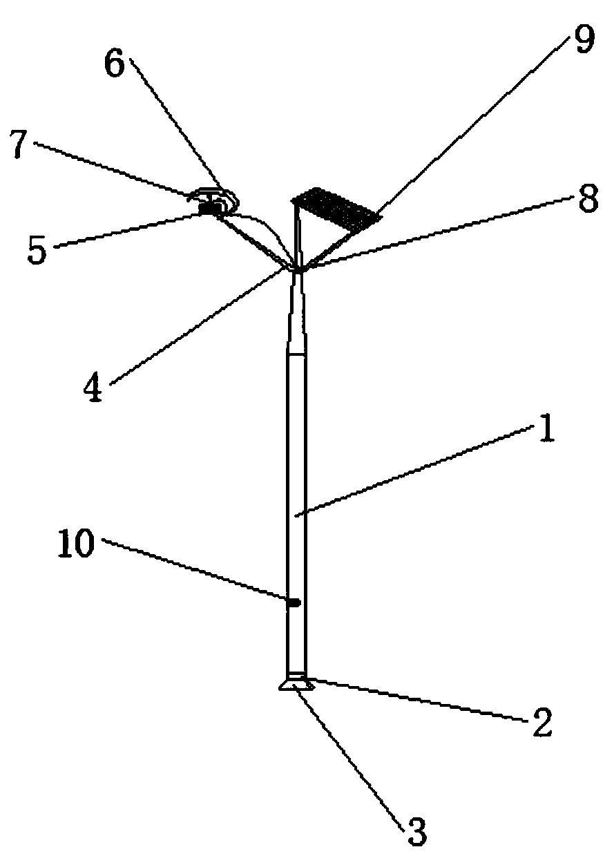
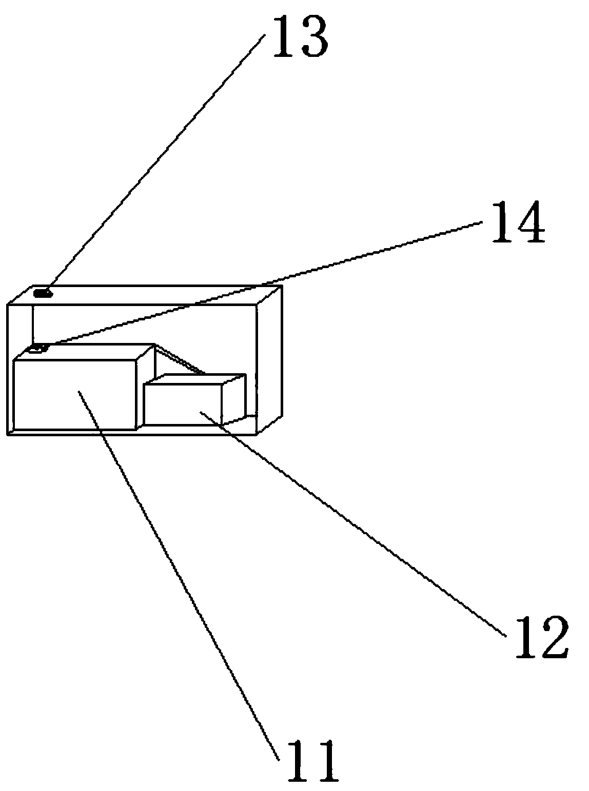
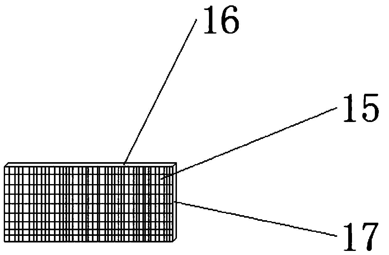
[0018] see Figure 1-3 , the present invention provides a technical solution: a solar energy-saving road lighting lamp, comprising a utility pole main body 1, the lower end of the utility pole main body 1 is provided with a base 3, the base 3 is fixedly connected with the utility pole main body 1, and the upper end of the utility pole main body 1 is provided with There is a lamp arm 4, and the lamp arm 4 is fixedly connected with the utility pole main body 1. The upper end of the utility pole main body 1 is provided with a protective cover 6, and the protective cover 6 is tightly welded with ...
PUM
 Abstract
Description
Claims
Application Information