
A multi-channel trigger current testing system and its debugging and testing method

A technology for triggering current and testing system, applied in the direction of using digital measurement technology for measurement, measurement device, measurement of electrical variables, etc., can solve the problem of inability to realize multi-channel long-term sampling experiments, etc., to make up for a single sensor and data acquisition circuit. Inadequate, achieve the effect of optimizing the range and accuracy, and data accuracy

Active Publication Date: 2022-05-03
DONGFENG COMML VEHICLE CO LTD
View PDF6 Cites 0 Cited by
  • Summary
  • Abstract
  • Description
  • Claims
  • Application Information

AI Technical Summary

Problems solved by technology

[0007] The purpose of the present invention is to overcome the problem in the prior art that multi-channel long-time sampling experiments cannot be realized, and provide a multi-channel trigger current testing system capable of realizing multi-channel wide-time domain sampling experiments and its debugging and testing methods

Method used


Image

  • A multi-channel trigger current testing system and its debugging and testing method
  • A multi-channel trigger current testing system and its debugging and testing method
  • A multi-channel trigger current testing system and its debugging and testing method

Examples


Embodiment 1

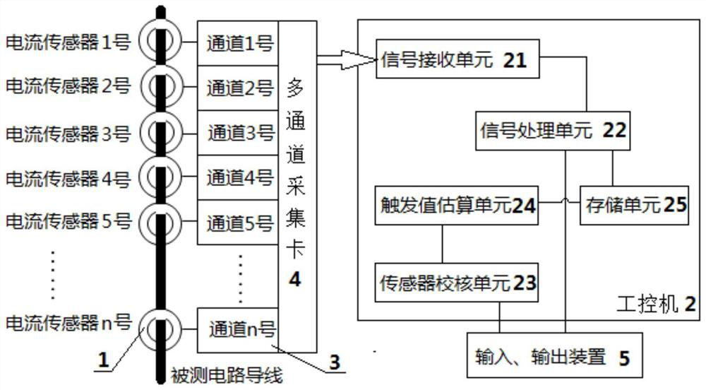
[0062] A multi-channel trigger current testing system includes a current sensor 1 and an industrial computer 2, and the current sensor 1 is connected to the industrial computer 2 for signals; the test system includes a plurality of current sensors 1, and the plurality of current sensors 1 pass through Corresponding sampling channel 3 is connected with multi-channel acquisition card 4 signals, and described multi-channel acquisition card 4 is connected with industrial computer 2 signals, and described industrial computer 2 is connected with input and output device 5 signals; Described current sensor 1 is non-contact type sensor; the industrial computer 2 includes: a signal receiving unit 21, a signal processing unit 22, a sensor checking unit 23, a trigger value estimation unit 24 and a storage unit 25, and the signal receiving unit 21 signal input terminal is connected to a multi-channel acquisition card The signal output end of 4 is connected, and the signal output end of the ...

Embodiment 2

[0071] Embodiment 2 is basically the same as Embodiment 1, and its difference is:

[0072] The industrial computer 2 is an embedded industrial computer or a PC industrial computer;

[0073] The input and output devices 5 include: a keyboard, a mouse, a display, and a touch display.


PUM


Abstract

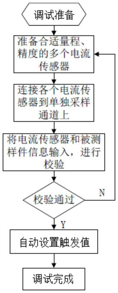
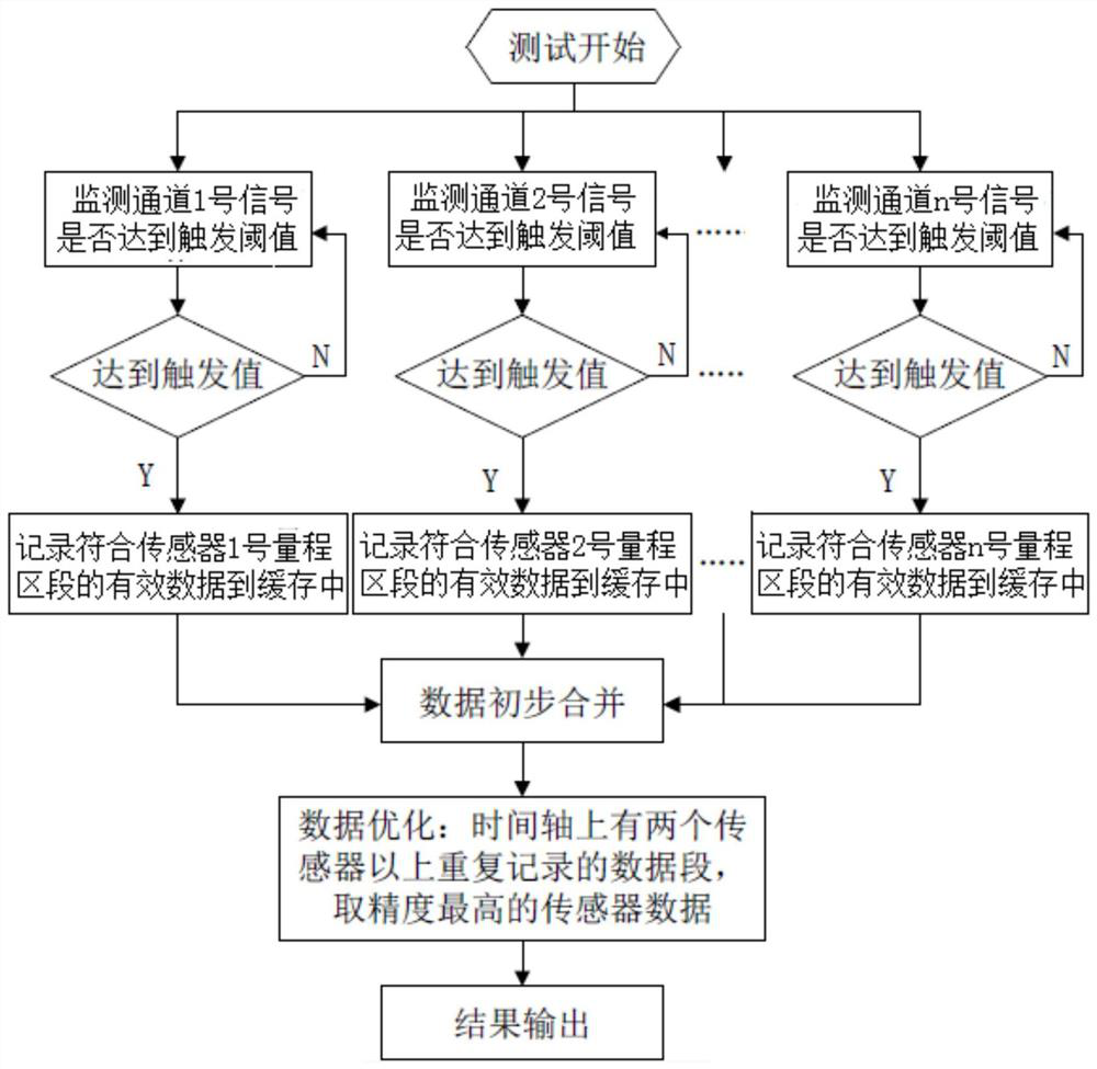
A multi-channel trigger current test system, the test system includes a plurality of current sensors, the plurality of current sensors are connected to a multi-channel acquisition card signal through their corresponding sampling channels, and the multi-channel acquisition card is connected to an industrial computer signal , the industrial computer is signal-connected with the input and output devices. Debugging includes three steps: building a test device, calibrating sensors, and generating trigger thresholds, and testing includes two steps: running test and data integration. This design not only has a reasonable structure, can realize wide range, high precision and long-time monitoring, but also can automatically check the data and realize the automation of the testing process.

Description

technical field [0001] The invention relates to a multi-channel trigger current testing system and its debugging and testing method, which is particularly suitable for improving the testing accuracy of equipment and enlarging the testing range and testing time domain. Background technique [0002] High-current, micro-current, and transient steady-state current measurement technology is an important part of the field of modern automotive electronics. It is of great significance in ensuring the safe operation of vehicle electrical systems, improving product reliability, saving energy and reducing consumption. According to the frequency characteristics, the current of the vehicle can be divided into steady-state current and transient current; according to the size, it can be divided into low-voltage small current, low-voltage large current, and static current. The amplitude span is from mA level to above 1000A, and the detection time is from From milliseconds to hours. [0003...

Claims


Application Information

Patent Timeline
Patent Type & Authority Patents(China)
IPC IPC(8): G01R19/25G01R35/00
CPCG01R19/25G01R35/005
Inventor 郄鹤峰王磊
Owner DONGFENG COMML VEHICLE CO LTD
Learn More