A method and system for realizing dynamic adjustment of electronic cam

An electronic cam and dynamic adjustment technology, which is applied in the direction of control/regulation system, general control system, program control, etc., can solve the problems such as difficult to realize the dynamic adjustment of the electronic cam, and difficult to meet the dynamic control of the axis, so as to improve the flexibility and expand the application range effect

Active Publication Date: 2021-05-18
HUAZHONG UNIV OF SCI & TECH
View PDF7 Cites 0 Cited by
  • Summary
  • Abstract
  • Description
  • Claims
  • Application Information

AI Technical Summary

Problems solved by technology

[0003] Under the process of industrial automation, the performance of control systems and servos has been widely improved. Various light and heavy industries have also put forward higher speed, higher precision, and higher stability requirements for industrial control. The traditional motion control card based The electronic cam implementation scheme combined with the servo motor is difficult to complete the calculation or obtain the next task in a short time, or to add a load to the main control task, and then it is difficult to realize the dynamic adjustment of the electronic cam, and it is difficult to meet the dynamic control of axes in more fields. need

Method used


Image

  • A method and system for realizing dynamic adjustment of electronic cam
  • A method and system for realizing dynamic adjustment of electronic cam
  • A method and system for realizing dynamic adjustment of electronic cam

Examples


Embodiment Construction

[0036] In order to make the object, technical solution and advantages of the present invention clearer, the present invention will be further described in detail below in conjunction with the accompanying drawings and embodiments. It should be understood that the specific embodiments described here are only used to explain the present invention, not to limit the present invention. In addition, the technical features involved in the various embodiments of the present invention described below can be combined with each other as long as they do not constitute a conflict with each other.

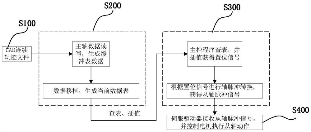
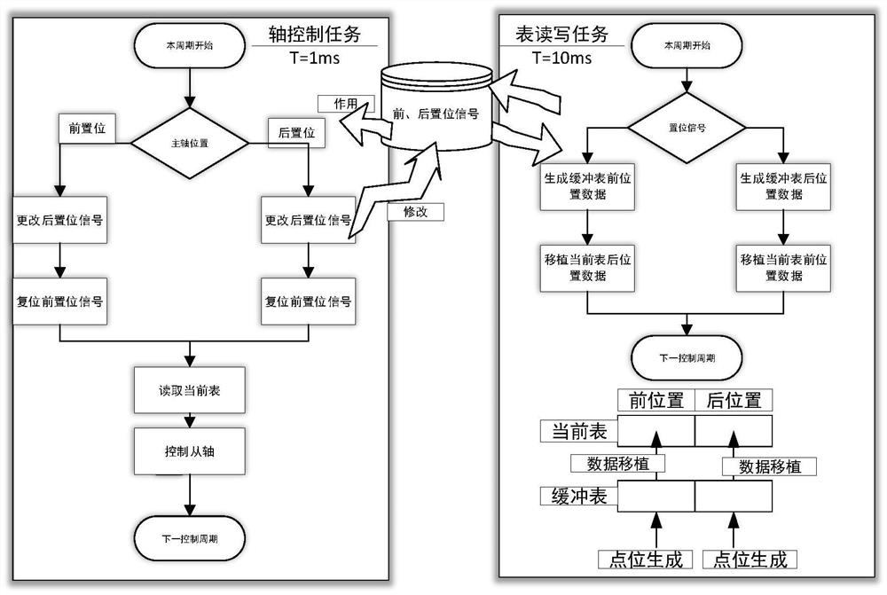
[0037] The electronic cam dynamic adjustment system of the present invention comprises an electronic cam state machine module, a cam table data structure module and a read-write module.

[0038]The electronic cam state machine module includes a disengagement state and an engagement state, wherein the disengagement state includes the state Disabled at initial power-on, the state StandStill after ...


PUM


Abstract

The invention belongs to the field of cam automation control, and specifically discloses a method and a system for realizing the dynamic adjustment of an electronic cam. The method includes: preparing spindle CAD continuous trajectory files for multiple tasks, the main control program sequentially generates buffer table data for multiple tasks, and then performs data transplantation on the buffer table data according to a set signal to generate an axis control task The current table data, and the current table data read by it are interpolated to obtain the set signal of the main shaft, and then the set signal of the main shaft is converted to the axis pulse to obtain the pulse signal of the slave axis to control the motor Execute slave axis actions. The system includes CAD continuous track files, a table reading and writing module, a main control module, a servo driver and a motor. The invention realizes the dynamic adjustment of the cam by dynamically changing the data table or parameters, improves the flexibility of the function of the electronic cam, and expands its application range.

Description

technical field [0001] The invention belongs to the field of cam automation control, and more specifically relates to a method and system for realizing the dynamic adjustment of an electronic cam. Background technique [0002] The electronic cam is a software system that uses the constructed cam curve to simulate the mechanical cam to achieve the same relative motion between the camshaft and the main shaft of the mechanical cam system. Compared with mechanical cams, electronic cams are more flexible, which is reflected in the realization of curve modeling practical software, low cost, reusable and high precision. Therefore, electronic cams can replace mechanical cams and are widely used in mechanical processing, water conservancy and hydropower, printing, Sewing industry. [0003] Under the process of industrial automation, the performance of control systems and servos has been widely improved. Various light and heavy industries have also put forward higher speed, higher pr...

Claims


Application Information

Patent Timeline
Patent Type & Authority Patents(China)
IPC IPC(8): G05B19/4097
CPCG05B19/4097G05B2219/34341
Inventor 王晓宇高朝阳陈雨
Owner HUAZHONG UNIV OF SCI & TECH
Why Eureka
Try Eureka