Sprayer

A sprinkler and sprinkler component technology, applied in the field of sprinklers, can solve the problems of low waste gas treatment efficiency, uneven waste gas flow rate, and fast moving speed of waste gas, etc.

Active Publication Date: 2020-01-07
山东圣大环保工程有限公司
View PDF13 Cites 0 Cited by
  • Summary
  • Abstract
  • Description
  • Claims
  • Application Information

AI Technical Summary

Problems solved by technology

However, in the existing spraying process, the exhaust gas stays in the spray tower for a short time, the exhaust gas moves fast, and the exhaust gas flow rate is uneven everywhere, and the exhaust gas treatment efficiency is low.

Method used


Image

  • Sprayer
  • Sprayer
  • Sprayer

Examples


Embodiment 1

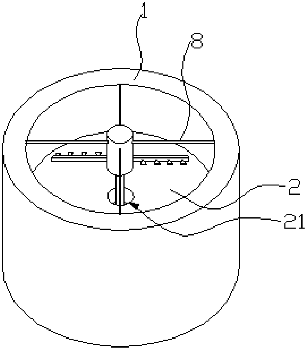
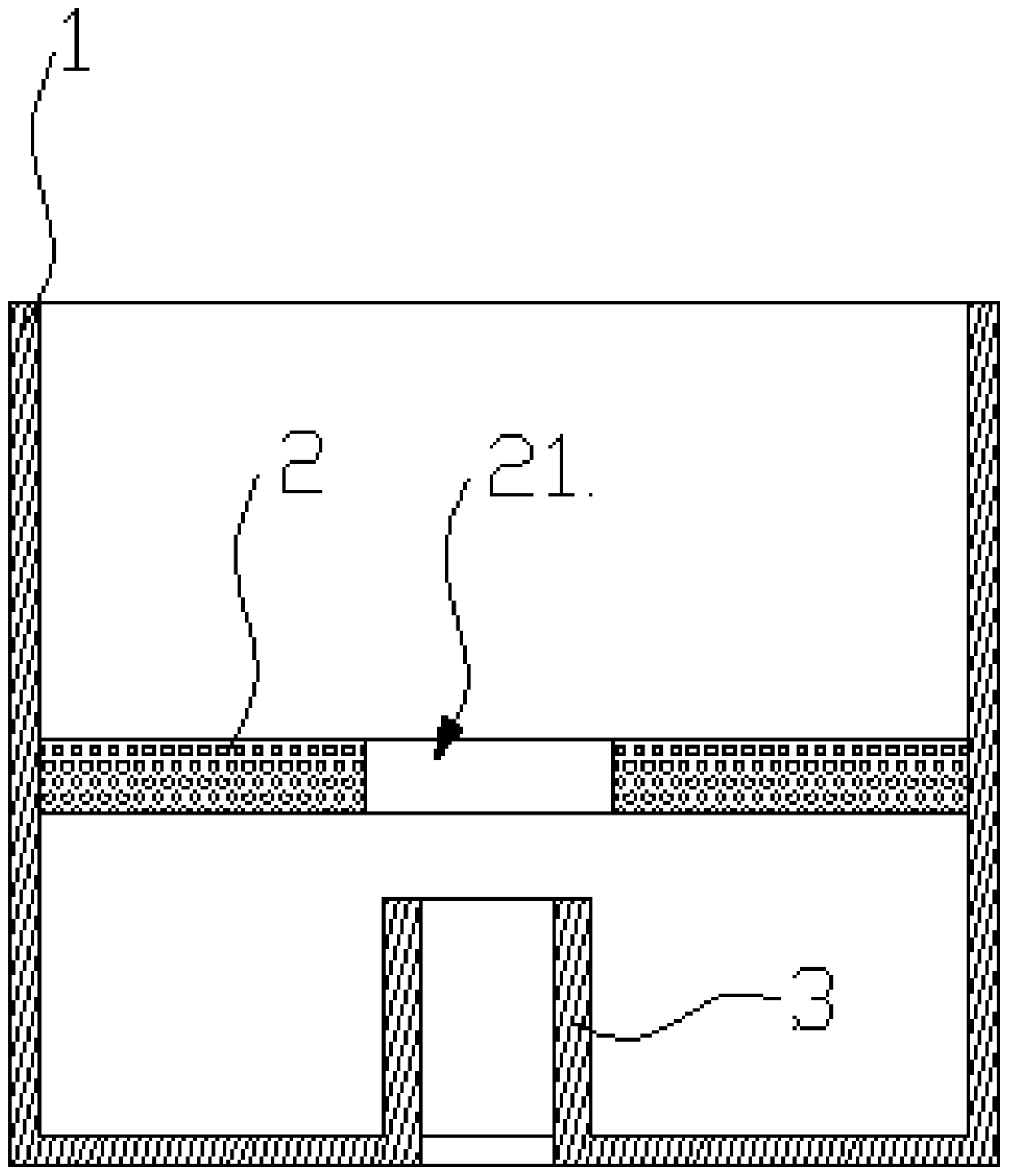
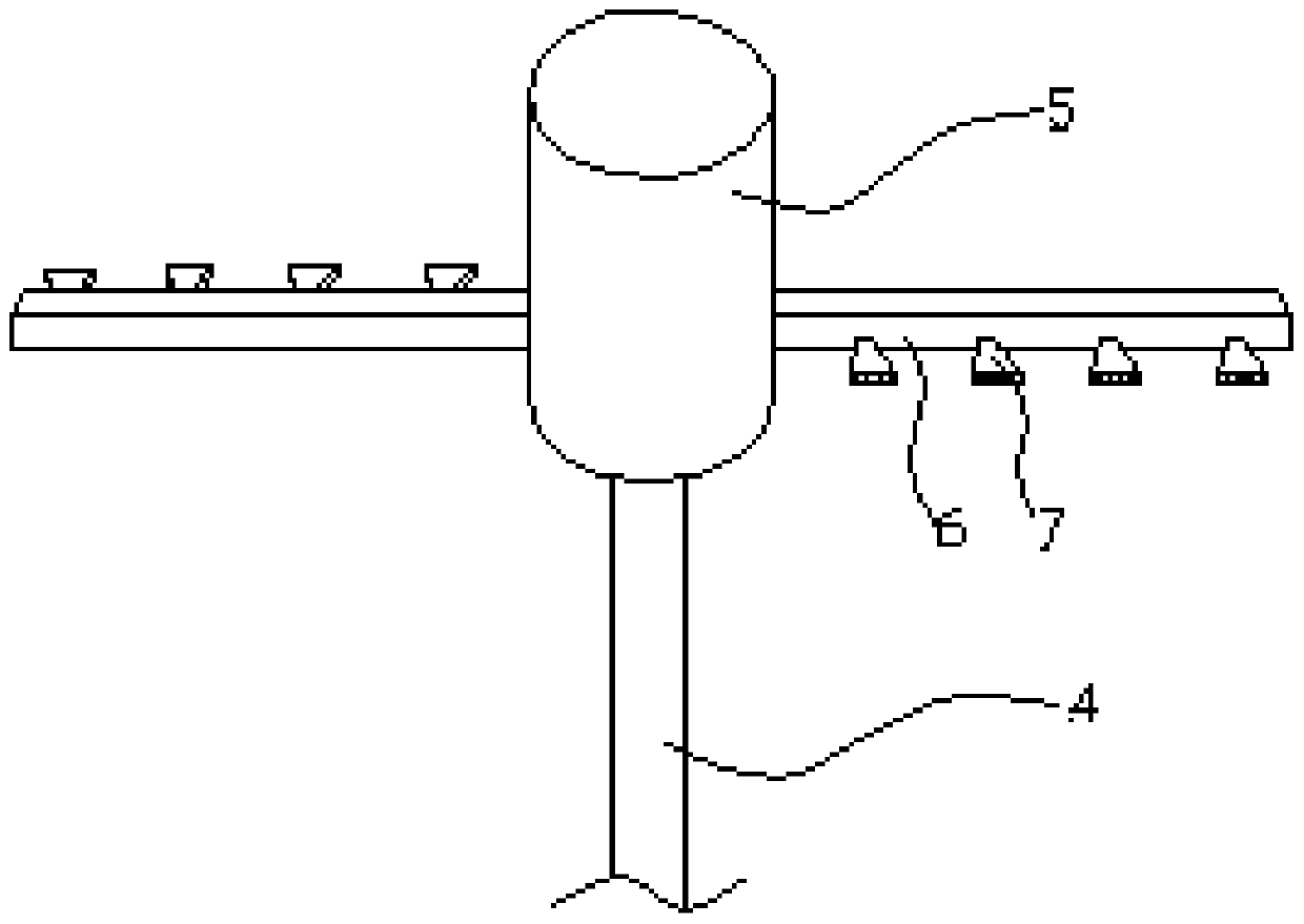
[0029] Such as figure 1 As shown, this embodiment provides a sprinkler, which includes a tower body 1, a water distribution plate 2 and a spray assembly located in the tower body 1, and the water distribution plate 2 is arranged laterally on the tower body 1, the water distribution plate 2 divides the cavity in the tower body 1 into an upper cavity and a lower cavity, and the water distribution plate 2 is provided with a There are multiple water holes in the cavity. In this embodiment, in order to prevent the medicine from clogging the water holes, the water holes can be square or other irregular shapes. The spray head 7 of the spray assembly is located on the upper part of the water distribution plate 2 , and the spray head 7 is used for spraying chemicals to the water distribution plate 2 . The bottom of the tower body 1 is provided with an air inlet, and an upwardly extending spacer ring 3 is arranged on the air inlet hole, and the space between the spacer ring 3 and the s...


PUM


Abstract

The invention relates to the field of environmental protection equipment, and particularly provides a sprayer which comprises a tower body, a water distribution plate and a spraying assembly; the water distribution plate and the spraying assembly are located in the tower body, the water distribution plate is transversely arranged in the tower body and divides the tower body into an upper cavity and a lower cavity, and a plurality of water holes are formed in the water distribution plate; a spray head of the spraying assembly is used for spraying chemicals to the water distribution plate. An air inlet hole is formed in the bottom of the tower body, a spacer ring extending upwards is arranged on the air inlet hole, a water collecting tank is formed in a space between the spacer ring and theside wall of the tower body, and the water collecting tank is used for collecting chemicals falling from the water holes. According to the sprayer, due to the arrangement of the water distribution plate, the residence time of waste gas in the tower body can be prolonged; meanwhile, the waste gas flow speed can be controlled, and the waste gas uniformly flows everywhere in the tower body; furthermore, the water distribution plate can also control the spraying direction of the chemicals, so that the chemicals uniformly drip at each part of the lower cavity. Waste gas is subjected to spraying treatment through the sprayer, and the cooling and dust removing effects are obviously superior to those of a spraying tower in the prior art.

Description

technical field [0001] The invention relates to the field of waste gas treatment, in particular to a shower for treating waste gas by spraying. Background technique [0002] Spraying is one of the conventional processes for waste gas treatment. The existing spraying treatment is to input the waste gas from the bottom of the spray tower into the cavity of the spray tower, and spray chemicals into the cavity of the spray tower through the nozzle to make the waste gas Harmful substances in the medicament dissolve in the medicament or react with the drug in the medicament, and the exhaust gas after final treatment is discharged from the upper part of the spray tower. However, in the existing spraying process, the waste gas stays in the spray tower for a short time, the moving speed of the waste gas is fast, and the flow rate of the waste gas is uneven everywhere, and the waste gas treatment efficiency is low. Contents of the invention [0003] The main purpose of the present ...

Claims


Application Information

Patent Timeline
Patent Type & Authority Applications(China)
IPC IPC(8): B01D53/78
CPCB01D53/78
Inventor 王静怡马桂英郑海勇冷添邵明明郑莉程守鹏巩明贵郑成助张家春王绍著
Owner 山东圣大环保工程有限公司
Why Eureka
Try Eureka