Friction stir welding stirring head with integrated welding and milling

A technology of friction stir welding and stirring head, applied in welding equipment, non-electric welding equipment, other manufacturing equipment/tools, etc., can solve the problems of increased production cost, easy failure of cutting groove, uneven pressing amount, etc., and achieve reduction in production The effect of reducing cost, reducing production takt time and improving production efficiency

Active Publication Date: 2020-01-07
AEROSPACE ENG EQUIP SUZHOU CO LTD
View PDF7 Cites 11 Cited by
  • Summary
  • Abstract
  • Description
  • Claims
  • Application Information

AI Technical Summary

Problems solved by technology

[0003] However, in the process of friction stir welding, due to factors such as the unevenness of the welding material and the excessive press-in amount of the traditional stirring head, the amount of flash generated during welding is too large, which requires additional cleaning procedures after welding, which prolongs the welding process. Production tact, increase production cost
The existing one-piece stirring head has a cutting groove on the shaft shoulder, and the cutting groove will directly participate in the welding, which will affect the welding effect and cause poor surface formation; the cutting groove and the shaft shoulder are on the same plane, and the tolerance to the plane of the welding sample is weak; The groove is not separated from the shaft shoulder, and the range of the cutting groove formed by the contact between the cutting groove and the sample is limited. After welding, it is easy to accumulate material in the cutting groove and stick to the knife. After a certain period of welding, the cutting groove is prone to failure

Method used


Image

  • Friction stir welding stirring head with integrated welding and milling
  • Friction stir welding stirring head with integrated welding and milling
  • Friction stir welding stirring head with integrated welding and milling

Examples


Embodiment Construction

[0022] The implementation of the technical solution will be further described in detail below in conjunction with the accompanying drawings. The following examples are only used to illustrate the technical solution of the present invention more clearly, but not to limit the protection scope of the present invention.

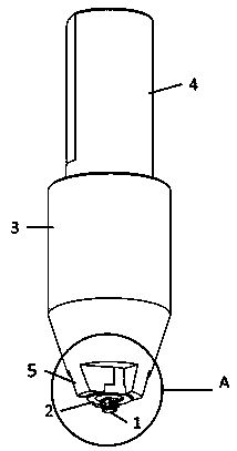
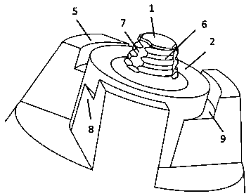
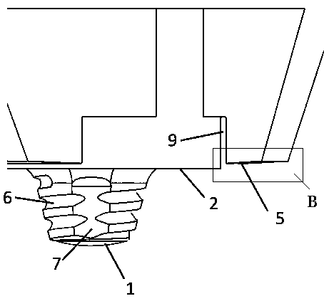
[0023] Such as Figure 1~3 As shown, a welding and milling integrated friction stir welding stirring head includes: clamping end 4, support body 3, shaft shoulder 2, stirring pin 1 and milling teeth 5; the front end of the stirring pin 1 and the shaft shoulder 2 are integral connected, the rear end of the shoulder 2 is connected to the small end of the tapered end of the support body 3, the large end of the tapered end of the support body 3 is connected to the cylindrical end, and the cylindrical end of the support body 3 is connected to the clamping end 4, the The shaft shoulder 2 is arranged in the middle of the small end of the tapered end of the support body...


PUM


Abstract

The invention discloses a friction stir welding stirring head with integrated welding and milling. The friction stir welding stirring head comprises a clamping end, a supporting body, a shaft shoulder, a stirring needle and milling teeth, wherein the stirring needle is integrally connected with the front end of the shaft shoulder, the rear end of the shaft shoulder is connected with the small endof a conical end of the supporting body, the large end of the conical end of the supporting body is connected with a cylindrical end, the cylindrical end of the supporting body is connected with the clamping end, the shaft shoulder is arranged in the middle of the front end of the conical end, and a plurality of milling teeth are uniformly arranged around the shaft shoulder. According to the milling tooth uniformly distributed outside the shaft shoulder of the stirring head, as the shaft shoulder and the stirring needle rotate at a high speed, when a weld joint generates a flash in the rotating downward pressing process, large-area flash cutting is rapidly carried out on the edge of the welding seam, and the flash is discharged along the gap of the milling tooth, so that the process of mechanically removing the flash after the welding of a traditional stirring head is omitted.

Description

technical field [0001] The invention discloses a friction stir welding stirring head integrated with welding and milling, and relates to the technical field of friction stir welding. Background technique [0002] Friction stir welding is mainly aimed at the connection of non-ferrous metals such as aluminum alloys. Its advantages are that the weld seam formed is of good quality, high strength, small deformation, no pollution, no smoke and spatter during welding, high efficiency and simple operation, and low noise. , energy saving and environmental protection, etc., so the friction stir welding technology continues to expand in the application field. Stirring head is the core component directly involved in friction stir welding, and its structural design determines the quality of friction stir welding seam, welding process and its service life. [0003] However, in the process of friction stir welding, due to factors such as the unevenness of the welding material and the exce...

Claims


Application Information

Patent Timeline
Patent Type & Authority Applications(China)
IPC IPC(8): B23P23/04B23K20/12B23K20/26
CPCB23K20/12B23K20/1245B23K20/26B23P23/04
Inventor 李文晓徐晓霞王海波范美华林永勇王学吉胡霞
Owner AEROSPACE ENG EQUIP SUZHOU CO LTD
Why Eureka
Try Eureka