Automatic routing of wire harness of electrical system by means of two force control robots

A robot and wire laying technology, applied in general control systems, control/regulation systems, manufacturing wiring harnesses, etc., can solve problems such as inability to introduce, broken wires, and single metal wires, so as to avoid loop formation, avoid breakage, The Effect of Complexity Reduction

Active Publication Date: 2020-01-07
克龙贝格和舒伯特两合有限公司
View PDF7 Cites 0 Cited by
  • Summary
  • Abstract
  • Description
  • Claims
  • Application Information

AI Technical Summary

Problems solved by technology

[0004] Especially in the case of very thin wires with small cross-sections (for example 0.13mm2, 0.25mm2, 0.35mm2), when laying the wires manually on the mold base plate, it may occur that individual wires of the wires break in the cable until Damage due to complete breakage of the wire, since the tensile forces acting on the wire are usually not adequately monitored and therefore no corresponding measures can be introduced to prevent exceeding the maximum permissible tensile force for metal wires

Method used


Image

  • Automatic routing of wire harness of electrical system by means of two force control robots
  • Automatic routing of wire harness of electrical system by means of two force control robots
  • Automatic routing of wire harness of electrical system by means of two force control robots

Examples


Embodiment Construction

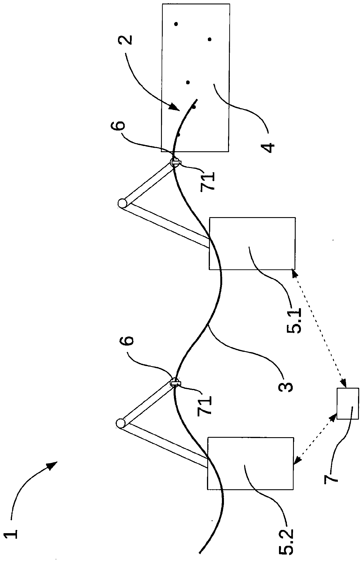
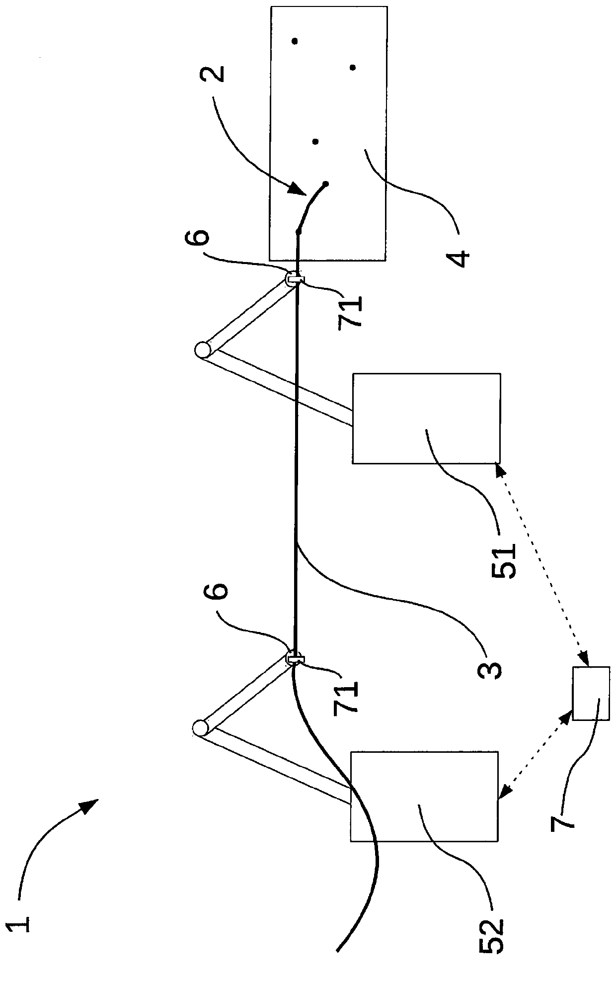
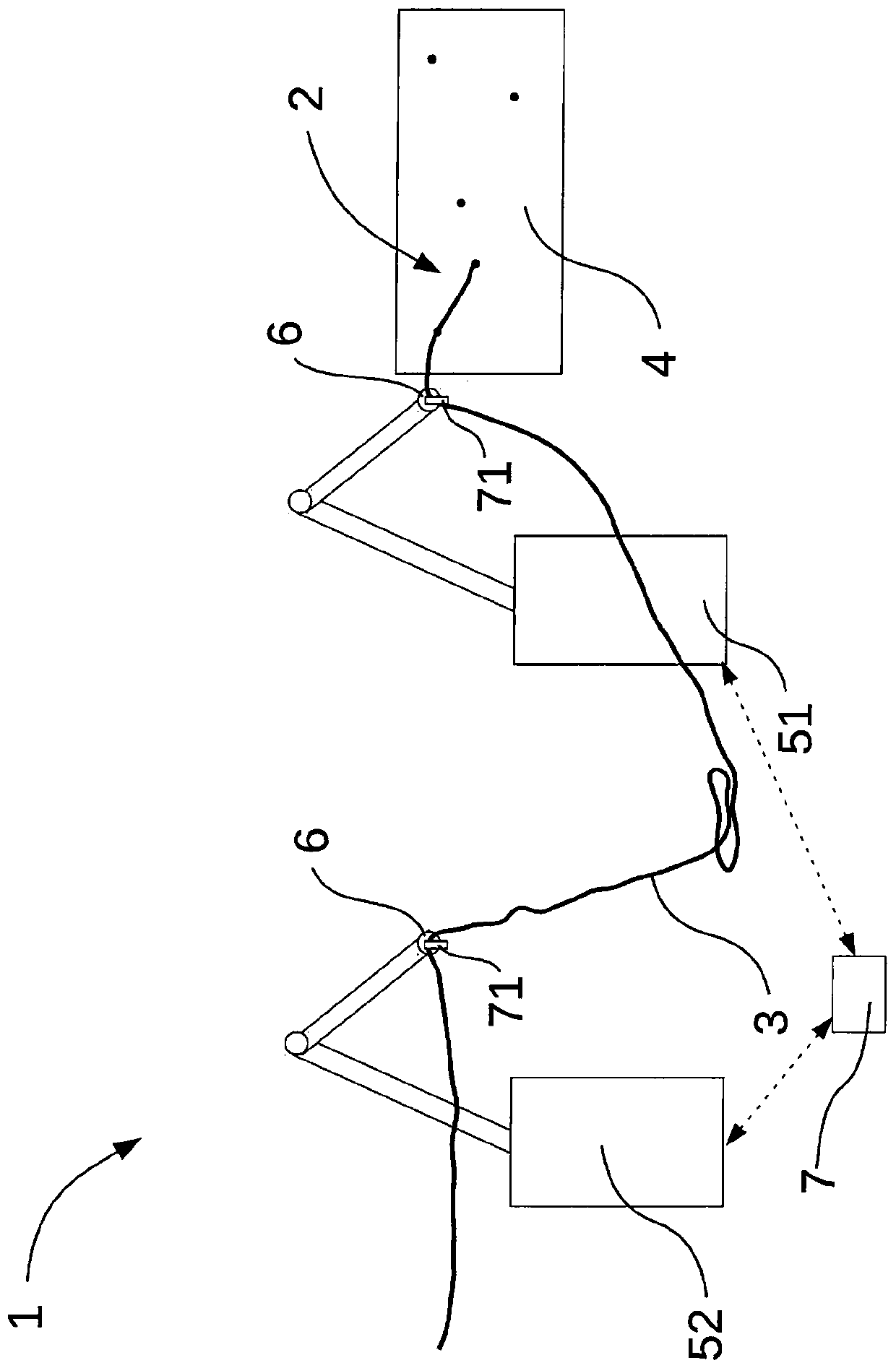
[0028] The invention is referenced below Figure 1 to 3 The description is based on exemplary embodiments, in which the same reference numerals indicate the same structural features and / or functional features.

[0029] figure 1 A schematic diagram of the wire laying system 1 for manufacturing the wire harness 2 in normal operation is shown, and the wire harness is composed of a plurality of cables and / or wires 3. The wire laying system 1 includes two robots 5.1, 5.2, which are assigned different control levels in the system. The robots 5.1, 5.2 are configured to have a grasping element 6 for grasping at least one electric wire 3 of the wire harness 2 for laying the electric wire 3 on the cable mold base plate 4.

[0030] The wire laying system 1 also has a common hierarchical control device 7, which controls the simultaneous movement and simultaneous grabbing of the grabbing elements 6 of the robots 5.1 and 5.2 based on the detected operating data during simultaneous wire processi...


PUM


Abstract

The invention relates to a wiring system (1) which is used for producing a wire harness (2) consisting of a plurality of cables and / or wires (3), the wire laying system comprises at least two robots (5.1, 5.2, 5.3,...). The robot is assigned different control levels in the system, and the robot is designed with a gripping element (6) for gripping at least one electrical wire (3) of the wire harness for laying the electrical wire (3) on a cable mold base (4) or directly in an end application.

Description

Technical field [0001] The present invention relates to a wiring system for manufacturing or installing a wire harness composed of a plurality of cables and / or wires, for example, for laying wires on a cable mold base plate or directly in an end application. Background technique [0002] Such wiring systems are known from the prior art. [0003] The complete monitoring and documentation of the wiring process is expected, because in the future, it is necessary to ensure functional safety, especially in the part of the circumference of the wiring harness, which is responsible for surrounding environment recognition and steering and control in automatic control vehicles. move. This applies mainly to the forces and moments that occur during the wire-laying process, which forces and moments develop on the wires to be laid, for example by an assembler or a wire-laying robot, during pulling, for example. [0004] Especially in the case of very thin wires with small cross-sections (for exa...

Claims


Application Information

Patent Timeline
IPC IPC(8): B25J9/16B25J13/08B25J15/08H01B13/012
CPCB25J9/1602B25J9/1664B25J13/088B25J15/08H01B13/01209H01B13/01236B25J9/1682G05B2219/45097G05B2219/39109G05B2219/39112
Inventor D·贝希斯坦R·杰克
Owner 克龙贝格和舒伯特两合有限公司
Why Eureka
Try Eureka