Wear-resistant rope supporting device special for power transmission

A technology for preventing wear and supporting devices, applied in hoisting devices, portable lifting devices, overhead line/cable equipment, etc., can solve the problems of economic loss, staff injury, and high labor intensity, and achieve wear-resistant and convenient access. , the effect of reducing labor intensity

Active Publication Date: 2020-01-07
STATE GRID CORP OF CHINA +1
View PDF9 Cites 3 Cited by
  • Summary
  • Abstract
  • Description
  • Claims
  • Application Information

AI Technical Summary

Problems solved by technology

[0003] In the lifting process at noon, the existing technology usually uses insulated ropes as lifting tools, especially in live work. During the operation, the operator generally uses the bottom member of the transmission tower as a fulcrum for controlling the rope during the lifting process. , in order to achieve the purpose of lifting heavy objects, but because the bottom components of transmission towers are generally made of hard and rough materials, and the friction coefficient between the r

Method used


Image

  • Wear-resistant rope supporting device special for power transmission
  • Wear-resistant rope supporting device special for power transmission
  • Wear-resistant rope supporting device special for power transmission

Examples


Embodiment Construction

[0025] The following will clearly and completely describe the technical solutions in the embodiments of the present invention with reference to the accompanying drawings in the embodiments of the present invention. Obviously, the described embodiments are only some, not all, embodiments of the present invention.

[0026] In describing the present invention, it should be understood that the terms "upper", "lower", "front", "rear", "left", "right", "top", "bottom", "inner", " The orientation or positional relationship indicated by "outside", etc. is based on the orientation or positional relationship shown in the drawings, and is only for the convenience of describing the present invention and simplifying the description, rather than indicating or implying that the referred device or element must have a specific orientation, so as to Specific orientation configurations and operations, therefore, are not to be construed as limitations on the invention.

[0027] refer to Figure ...


PUM


Abstract

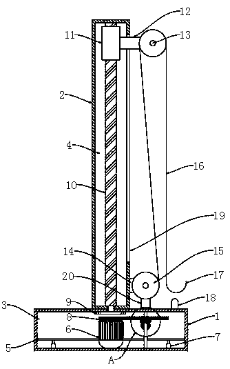
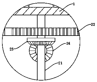
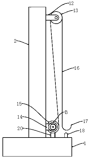
The invention discloses a wear-resistant rope supporting device special for power transmission. The device comprises a base and a power transmission rod tower fixedly connected to the upper end of thebase, a device cavity is formed in the side wall of the base, a cavity is formed in the side wall of the power transmission rod tower, a transverse plate is slidably connected to the opposite inner wall of the device cavity, the upper end of the transverse plate is fixedly connected with a forward and reverse rotating motor, the lower end of the transverse plate is fixedly connected to the innerbottom of the device cavity through an electric push rod, and a main gear is coaxially and fixedly connected to an output shaft of the forward and reverse rotating motor. By arranging a rope winding mechanism, a fixing mechanism, a clutch mechanism, a locking mechanism and multiple driving mechanisms, ropes can be routed from the two fixed pulleys without contact friction with the power transmission rod tower or the base, abrasion of the ropes is effectively prevented, automatic lifting of the ropes and automatic hoisting of heavy objects can be realized, manual operation is not needed, the labor cost is reduced, and danger is avoided.

Description

technical field [0001] The invention relates to the technical field of electric equipment, in particular to a rope support device for preventing abrasion in the field of power transmission. Background technique [0002] In the operation, maintenance and repair of overhead transmission lines, due to the high height of the transmission tower, the staff cannot carry more maintenance tools to climb to the top, so it is often necessary to use insulated ropes to lift heavy objects such as maintenance tools to the top of the tower to facilitate the operation of the staff. [0003] In the lifting process at noon, the existing technology usually uses insulated ropes as lifting tools, especially in live work. During the operation, the operator generally uses the bottom member of the transmission tower as a fulcrum for controlling the rope during the lifting process. , in order to achieve the purpose of lifting heavy objects, but because the bottom components of transmission towers ar...

Claims


Application Information

Patent Timeline
IPC IPC(8): B66D3/06B66D3/10H02G1/02
CPCB66D3/06B66D3/10B66D2700/028H02G1/02
Inventor 李龙
Owner STATE GRID CORP OF CHINA
Why Eureka
Try Eureka