Three-phase fluidized bed for sewage treatment

A three-phase fluidized bed and sewage treatment technology, which is applied in the directions of water/sewage multi-stage treatment, biological water/sewage treatment, water/sludge/sewage treatment, etc., can solve the problem of reduced treatment efficiency, reduced sewage treatment efficiency, Efficiency reduction and other issues, to achieve the effect of ensuring fluid treatment, improving treatment efficiency, and good treatment effect

Inactive Publication Date: 2020-01-07
曾新凤
View PDF0 Cites 3 Cited by
  • Summary
  • Abstract
  • Description
  • Claims
  • Application Information

AI Technical Summary

Problems solved by technology

[0003] However, when the existing three-phase fluidized bed is working, the sewage entering the spacer tube needs to overcome its own gravity and the resistance of the sewage above when it rises, resulting in a decrease in the efficiency of the sewage upflow, which leads to a decrease in the treatment efficiency, and also It is easy to reduce the treatment effect of the three-phase fluidized bed due to the backflow phenomenon of some sewage outlets, and when the fluid from the bottom of the divider 2 enters again, it contains a large amount of sludge, and the sludge that rises thereupon occupies the inner cavity of the divider 2 space, thus affecting the further treatment capacity of sewage, thereby reducing the efficiency of three-phase fluidized bed treatment of sewage

Method used


Image

  • Three-phase fluidized bed for sewage treatment
  • Three-phase fluidized bed for sewage treatment
  • Three-phase fluidized bed for sewage treatment

Examples


Embodiment Construction

[0016] The following will clearly and completely describe the technical solutions in the embodiments of the present invention with reference to the accompanying drawings in the embodiments of the present invention. Obviously, the described embodiments are only some, not all, embodiments of the present invention. Based on the embodiments of the present invention, all other embodiments obtained by persons of ordinary skill in the art without making creative efforts belong to the protection scope of the present invention.

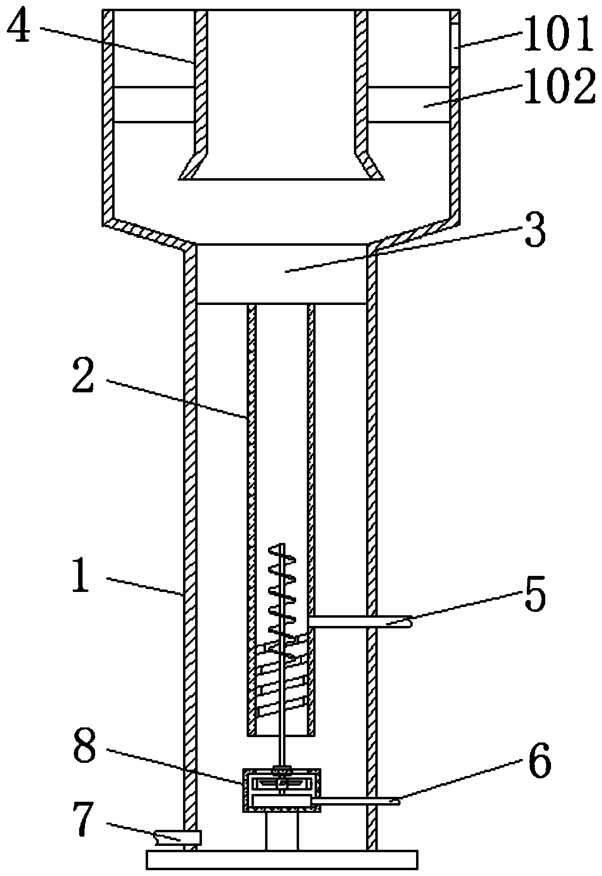
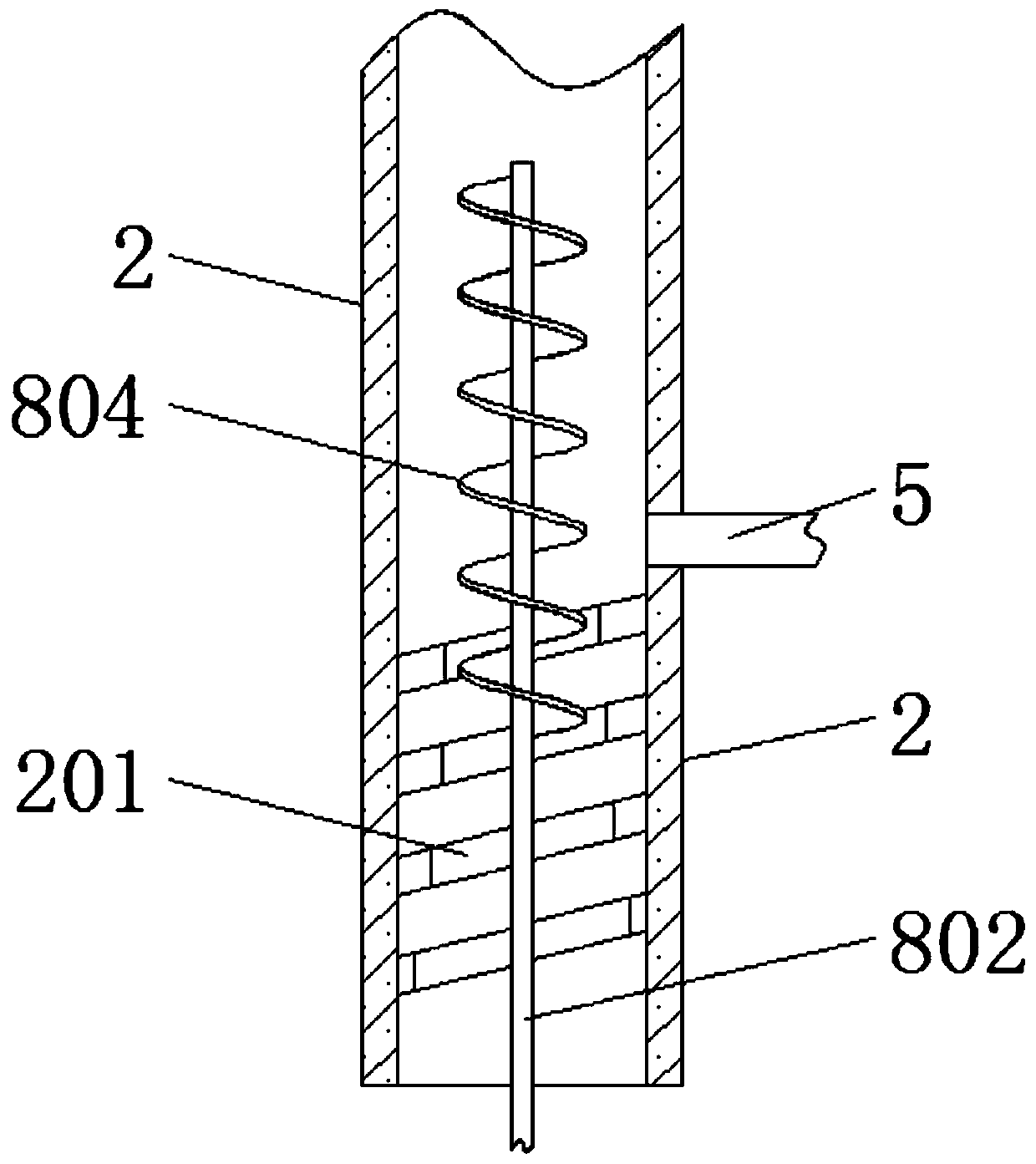
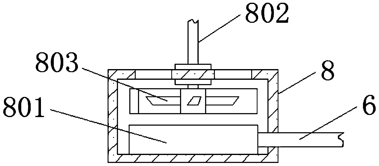
[0017] see Figure 1-3 , a three-phase fluidized bed for sewage treatment, comprising a separator pipe body 1, a divider pipe 2, a three-phase separator 3, an exhaust pipe 4, a water inlet pipe 5, an air inlet pipe 6 and a sewage discharge pipe 7, and a flow divider pipe 2. It is fixedly installed in the middle of the inner cavity of the separator tube body 1. The top of the spacer tube 2 is fixedly socketed with the bottom of the three-phase separator 3. The ...


PUM


Abstract

The invention relates to the field of sewage treatment equipment, and discloses a three-phase fluidized bed for sewage treatment. The three-phase fluidized bed for sewage treatment comprises a separator pipe body, a flow isolating pipe, a three-phase separator, an exhaust pipe, a water inlet pipe, an air inlet pipe and a blow-off pipe; the flow isolating pipe is fixedly arranged in the middle of an inner cavity of the separator pipe body, the top end of the flow isolating pipe is fixedly connected with the bottom of the three-phase separator in a sleeving mode, and the three-phase separator isarranged at the top of the inner cavity of the separator pipe body. According to the three-phase fluidized bed for sewage treatment, through the design of the water inlet pipe located in the flow isolating pipe, a spiral packing auger is driven to rotate by the air intake power of the air inlet pipe; fluid in the flow isolating pipe upwells under the rotating action of the spiral packing auger, so that the fluid in the flow isolating pipe overcomes the gravity and resistance of the fluid to keep an up-flow state, the lifting efficiency of the fluid in the inner cavity of the flow isolating pipe is effectively guaranteed, the effective reaction area of the fluid is guaranteed to be kept in a large state, and the treatment effect of the three-phase fluidized bed is good.

Description

technical field [0001] The invention relates to the field of sewage treatment equipment, in particular to a three-phase fluidized bed for sewage treatment. Background technique [0002] Three-phase fluidized bed is a kind of three-phase separation equipment commonly used in the field of sewage treatment, also known as air flow dynamic fluidized bed, sewage and air enter the bed simultaneously under the action of air flow, gas, liquid, solid (biofilm carrier three The phases are stirred and contacted, and an upflow is generated to circulate the treatment bed in the bed. In this process, the degradation reaction of organic pollutants occurs. Due to the strong friction between the carriers, the biofilm falls off in time, and no additional film removal equipment is required. , and its specific working principle is as follows (refer to Figure 4 ): Sewage is injected through the water inlet pipe 5, and at the same time, gas is introduced from the inlet pipe 6. Under the action of...

Claims


Application Information

Patent Timeline
Patent Type & Authority Applications(China)
IPC IPC(8): C02F9/14C02F101/30
CPCC02F1/001C02F3/1236C02F3/201C02F2101/30
Inventor 曾新凤
Owner 曾新凤
Why Eureka
Try Eureka