
Yarn breakage feeding stop signal control device for spinning frame

A signal control and spinning frame technology, applied in textiles and papermaking, etc., can solve problems such as dense components, large load current, and complicated processes

Pending Publication Date: 2020-01-07
杭州吉谦智能装备有限公司
View PDF0 Cites 0 Cited by
  • Summary
  • Abstract
  • Description
  • Claims
  • Application Information

AI Technical Summary

Problems solved by technology

[0003] 1. The drive circuit is controlled by an eight-way NPN Darlington connected transistor array series drive integrated circuit, and the maximum output current of this series of drive circuits is only 200mA, while the electromagnetic coil pull-in current needs to be more than 500mA. The drive control current is small and the load current is large. Unreasonable phenomenon, there is a great quality hidden danger
[0004] 2. Using 18 MOS tubes to control 18 electromagnetic coils, the control circuit is cumbersome and the components are dense, resulting in complex processes and difficult quality control in the production process.

Method used


Image

  • Yarn breakage feeding stop signal control device for spinning frame

Examples


Embodiment Construction

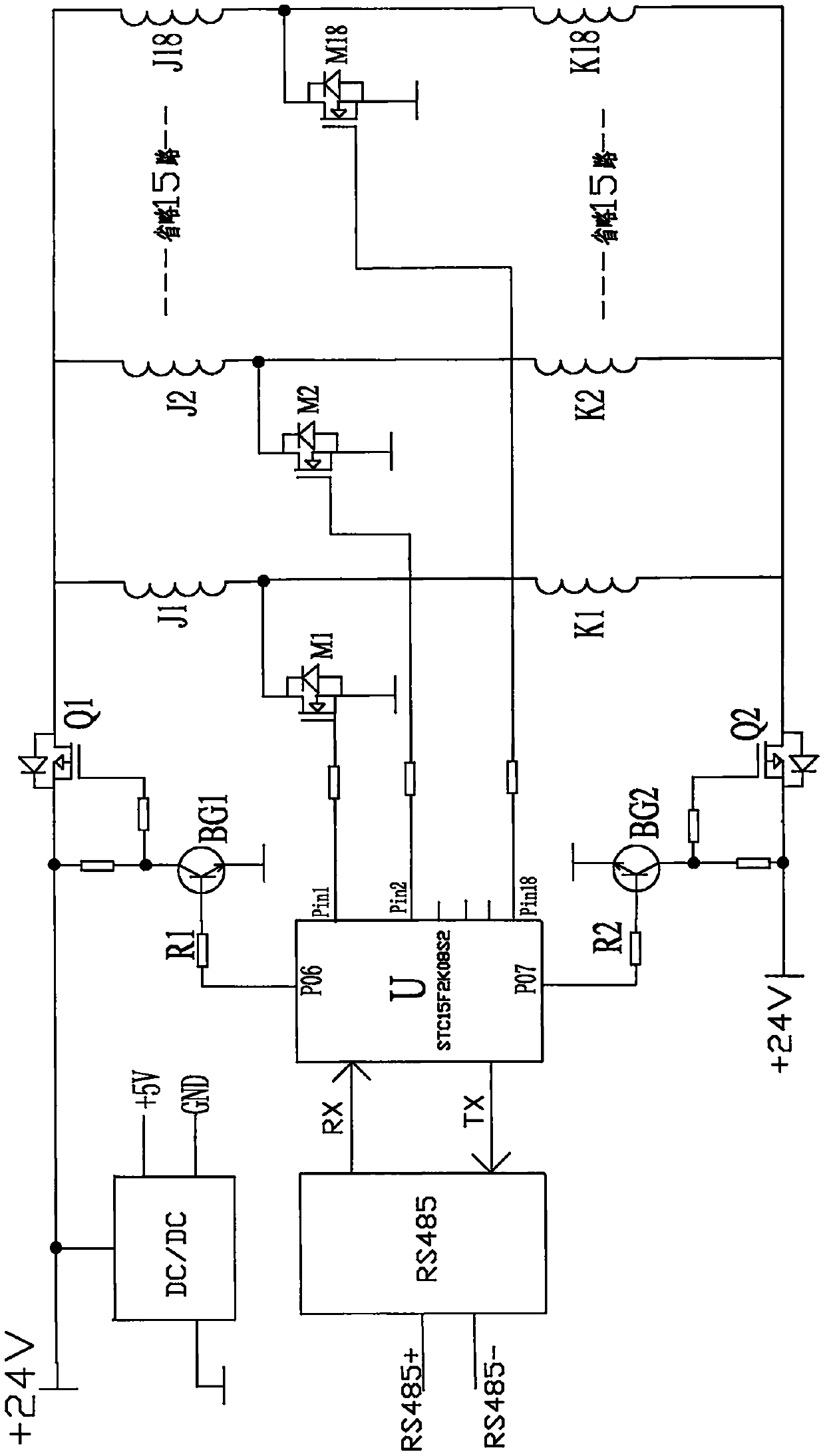
[0012] Such as figure 1 As shown, this embodiment includes a single-chip microcomputer U of model STC15F2K08S2, a first transistor BG1, a second transistor BG2, a first P-channel MOS transistor Q1, a second P-channel MOS transistor Q2, and an N-channel MOS transistor. Pipe Mi (i=1, 2...18), where:

[0013] The first output terminal P06 of the IO port of the single-chip microcomputer U is connected to the base of the first triode BG1 through the first current limiting resistor R1, and the collector of the first triode BG1 is connected to the first transistor BG1. The gate of the P-channel MOS transistor Q1 is connected, the emitter of the first triode BG1 is grounded, the source of the first P-channel MOS transistor Q1 is connected to the power supply terminal, and the first P-channel The drains of the MOS transistors Q1) are respectively connected to one end of the first group of electromagnetic coils Ji (i=1, 2...18).

[0014] The first P-channel MOS transistor Q1 is used a...


PUM


Abstract

The invention relates to a yarn breakage signal transmission control technique for a spinning frame, in particular to a yarn breakage feeding stop signal control device for the spinning frame. The yarn breakage signal transmission control technique comprises a single-chip microcomputer, a first triode, a first P-channel MOS tube and N-channel MOS tubes. A first output end of the single-chip microcomputer is connected with a gate of the first P-channel MOS tube through the first triode, and a drain of the first P-channel MOS tube is connected with one end of a first group of electromagnetic coils. Signal output ends of the single-chip microcomputer are in one-to-one corresponding connection with gates of the N-channel MOS tubes, and drains of the N-channel MOS tubes are in one-to-one corresponding connection with the other ends of the first group of electromagnetic coils. The yarn breakage feeding stop signal control device for the spinning frame is less in control circuit, high in output current and capable of adapting to large-current electromagnet driving. Compared with the prior art, the yarn breakage feeding stop signal control device has advantages of simple control circuit, low circuit manufacturing cost, low failure rate and the like.

Description

technical field [0001] The invention relates to a yarn breakage signal transmission control technology for a spinning frame, in particular to a yarn breakage stop-feeding signal control device for a spinning frame. Background technique [0002] In the current ring spinning frame, yarn breakage often occurs during the twisting process of the yarn. In order to detect the spindle position of the yarn breakage in time, a single spindle breakage detection of the spinning frame is installed at the twisting position of the spinning frame. The device is equipped with a yarn stop feeding mechanism on the route of roving delivery. After yarn breakage occurs, the single-spindle breakage detection device of the spinning frame transmits the signal to the PLC of the spinning frame, and then sends it to the yarn breakage stop feeding signal control device of each unit, and then the yarn breakage of the spinning frame stops. The feeding signal control device sends a signal to the electroma...

Claims


Application Information

Patent Timeline
Patent Type & Authority Applications(China)
IPC IPC(8): D01H13/18
CPCD01H13/188D01H13/18
Inventor 陈樊娟
Owner 杭州吉谦智能装备有限公司
Learn More