Communicated pulsating heat pipe type electronic component heat dissipation device

A technology for electronic components and heat sinks, applied in the field of connected pulsating heat pipe heat sinks for electronic components, capable of solving complex structures of air-cooled radiators and water-cooled radiators, lack of a good connection structure for heat dissipation bases, and heat loss of pulsating heat pipes Slow and other problems, to speed up the heat loss, speed up the heat loss, improve the effect of heat dissipation

Active Publication Date: 2020-01-07
CHANGCHUN INST OF TECH
View PDF5 Cites 0 Cited by
  • Summary
  • Abstract
  • Description
  • Claims
  • Application Information

AI Technical Summary

Problems solved by technology

[0002] CPU is one of the main devices of electronic computers. Its function is mainly to interpret computer instructions and process data in computer software. CPU appeared in the era of large-scale integrated circuits. The iterative update of processor architecture design and the continuous improvement of integrated circuit technology have prompted its Continuous development and improvement CPU has been developing rapidly since its birth. Currently, there are many types of radiators for desktop computer CPUs, and the technology is constantly maturing. There are self-cooling radiators, air-cooling radiators, water-cooling radiators, semiconductor radiators and heat pipe radiators. , as the heat sink continues to mature, with the development of electronic technology, the volume of electronic components is getting smaller and smaller, and the electronic assembly technology is also developing, making its integration density higher and higher, and the heat density it generates is also increasing , so the heat dissipation capacity of the radiator is extremely high. At present, air-cooled radiators and water-cooled radiators are mostly used in the market, but the structures of air-cooled radiators and water-cooled radiators are complex and inconvenient to use.
[0003] Currently authorized in China on April 1, 2007, the pulsating heat pipe radiator for electronic cooling with the authorized public number CN1946276A provides a new solution based on the above problems. It is equipped with cooling fins, pulsating heat pipes and a heat dissipation base. , easy to use, and convenient to dissipate heat, but the patent still has the following problems during use: the outside of the heat dissipation base lacks a good connection structure, and the heat dissipation base is connected with electronic components such as the CPU by adhesive bonding, which is inconvenient to install and disassemble; the pulsating heat pipe It is integrally formed by welding and is set in a serpentine circuit. The heat loss of the pulsating heat pipe is relatively slow, the heat dissipation time is relatively long, and the installation of the pulsating heat pipe is inconvenient.

Method used


Image

  • Communicated pulsating heat pipe type electronic component heat dissipation device
  • Communicated pulsating heat pipe type electronic component heat dissipation device
  • Communicated pulsating heat pipe type electronic component heat dissipation device

Examples


Embodiment

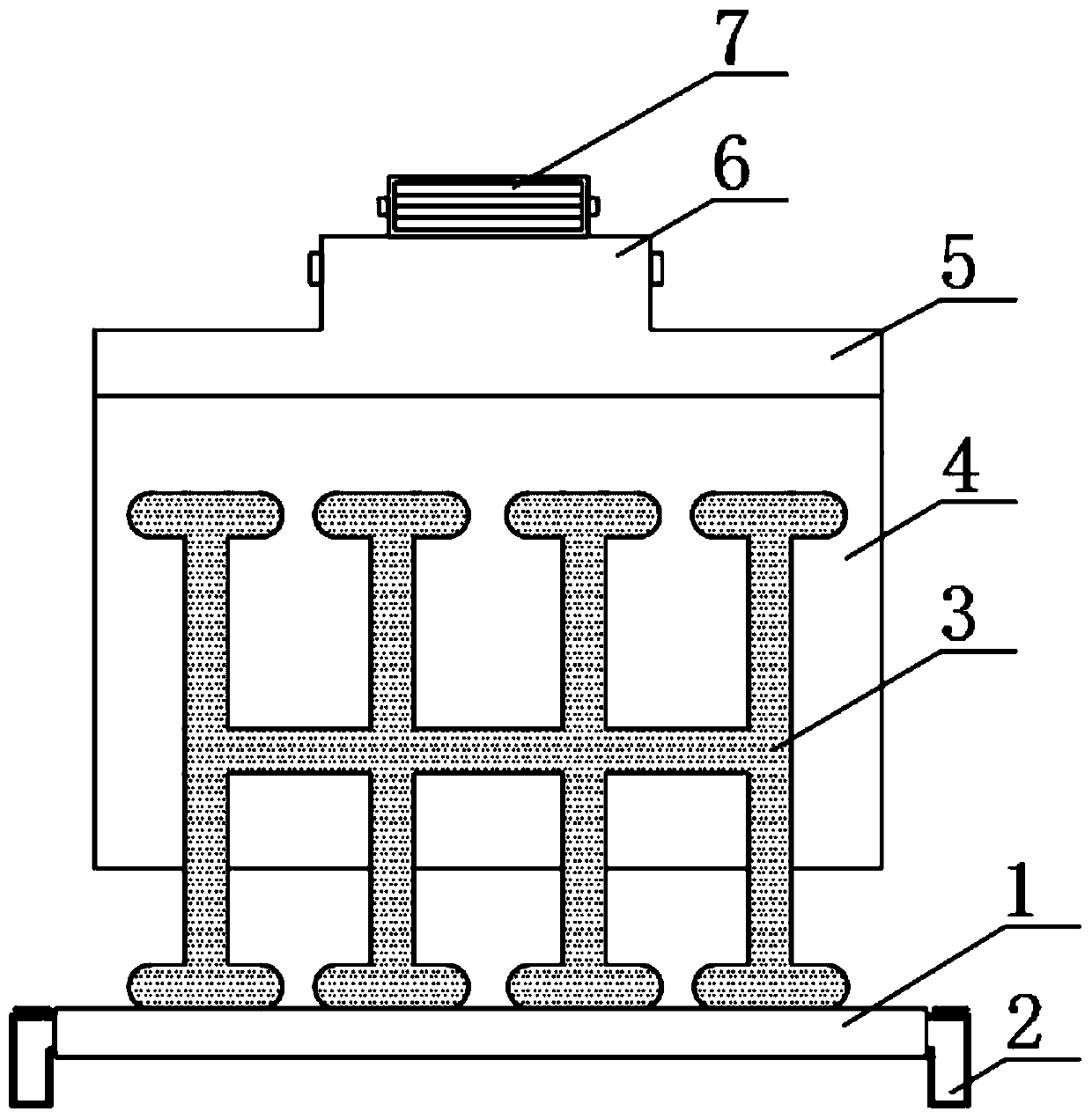
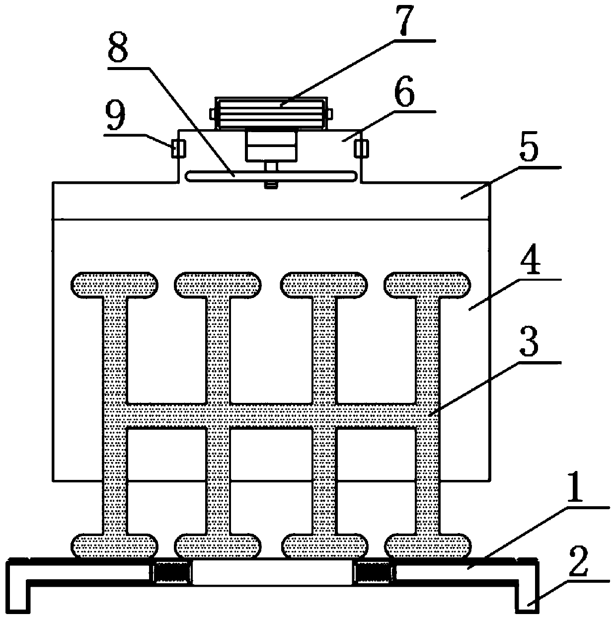
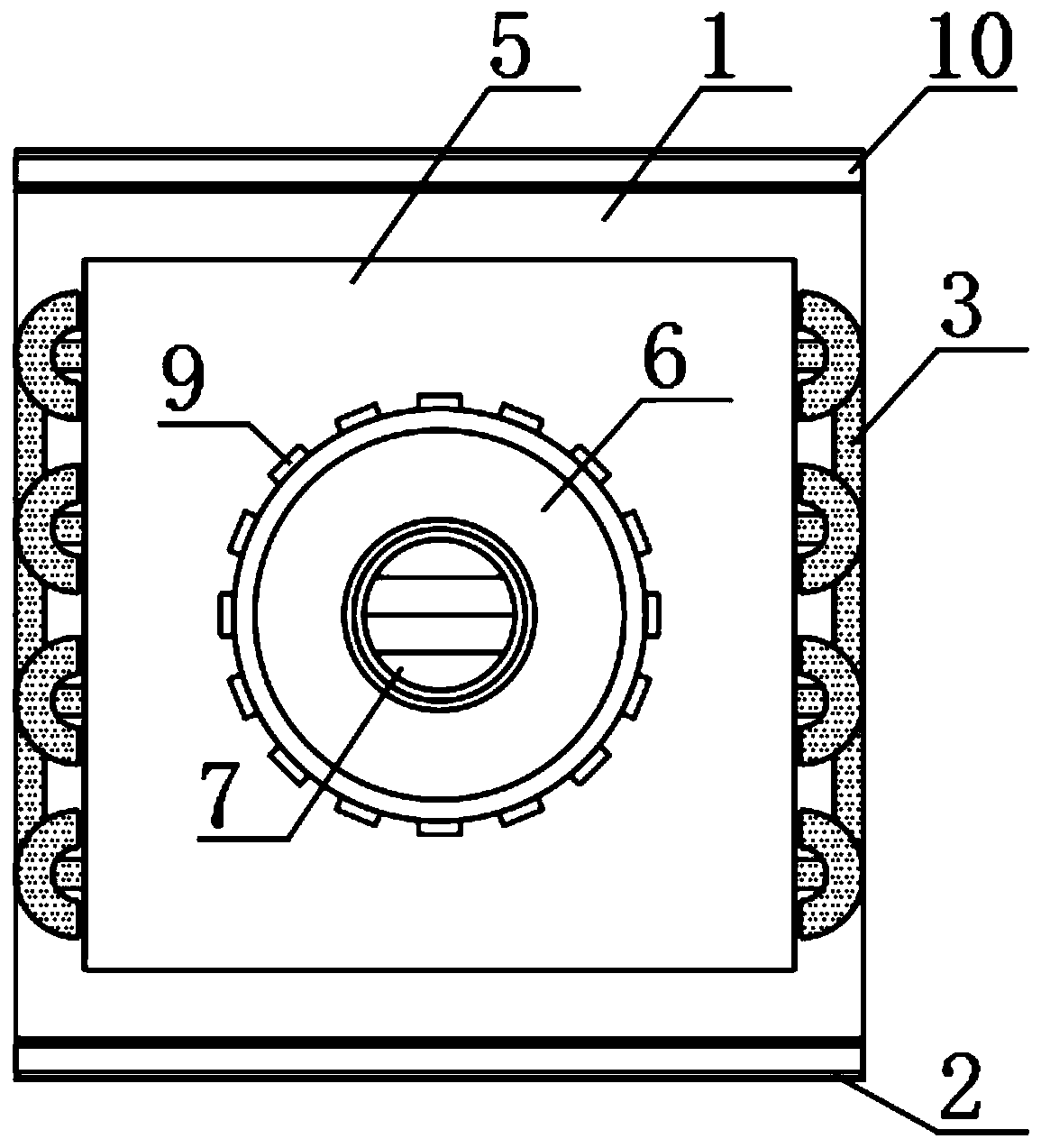
[0022] see Figure 1-Figure 6 , the present invention provides the following technical solutions: a connected pulsating heat pipe heat dissipation device for electronic components, including a heat dissipation base 1, a movable splint 2, a connected pulsating heat pipe 3, heat dissipation fins 4, a wind gathering cover 5, and an air supply box 6 With the electric motor 7, the inner two sides of the cooling base 1 are provided with movable grooves 11, the inner side of the movable groove 11 is provided with movable splints 2, and the inner other side of the movable groove 11 is provided with springs 12, and the top of the cooling base 1 A connected pulsating heat pipe 3 composed of several connected straight pipes and elbows arranged in an equal or staggered manner is provided. The upper end of the connected pulsating heat pipe 3 is provided with a number of uniformly arranged cooling fins 4. Above the connected pulsating heat pipe 3 The upper end of the heat dissipation fin 4 ...


PUM


Abstract

The invention belongs to the technical field of electronic component heat dissipation and particularly relates to a communicated pulsating heat pipe type electronic component heat dissipation device.The heat dissipation device comprises a heat dissipation base, a movable clamping plate, a communication type pulsating heat pipe, heat dissipation fins, an air gathering cover, an air supply box andan electric motor, wherein movable grooves are formed at two sides of the interior of the heat dissipation base correspondingly, the movable clamping plate is arranged on one side of the movable groove, a spring is arranged on the other side in the movable groove, the communicating type pulsating heat pipe composed of a plurality of connected straight pipes and elbows which are arranged in an equal or staggered mode is arranged above the heat dissipation base, an upper end of the communication type pulsating heat pipe is provided with a plurality of heat dissipation fins which are arranged atequal intervals, the air gathering cover is arranged above the communicating type pulsating heat pipe and located at upper ends of the heat dissipation fins, the air supply box is arranged at an upperend of the air gathering cover, the electric motor is arranged at an upper end of the air supply box, and a bottom end of the electric motor is located in the air supply box and is in transmission connection with a cooling fan through a transmission shaft. The heat dissipation device is advantaged in that the heat dissipation device is convenient to use, quick to start and quick in thermal response.

Description

technical field [0001] The invention belongs to the technical field of heat dissipation of electronic components, and in particular relates to a connected pulsating heat pipe type heat dissipation device for electronic components. Background technique [0002] CPU is one of the main devices of electronic computers. Its function is mainly to interpret computer instructions and process data in computer software. CPU appeared in the era of large-scale integrated circuits. The iterative update of processor architecture design and the continuous improvement of integrated circuit technology have prompted its Continuous development and improvement CPU has been developing rapidly since its birth. Currently, there are many types of radiators for desktop computer CPUs, and the technology is constantly maturing. There are self-cooling radiators, air-cooling radiators, water-cooling radiators, semiconductor radiators and heat pipe radiators. , as the heat sink continues to mature, with ...

Claims


Application Information

Patent Timeline
Patent Type & Authority Applications(China)
IPC IPC(8): H01L23/40H01L23/367H01L23/427H01L23/467
CPCH01L23/3672H01L23/40H01L23/427H01L23/467
Inventor 商福民刘建红范是龙杨清静刘超越武勇
Owner CHANGCHUN INST OF TECH
Why Eureka
Try Eureka