Positive electrode plate and lithium ion battery

A positive electrode sheet and positive electrode material technology, which is applied in the field of positive electrode sheets and lithium-ion batteries, can solve the problems of secondary particle crushing, fragility, and deterioration of lithium-ion battery gas production, achieve structural stability protection, and increase energy density , Improve the effect of gas production

Active Publication Date: 2020-01-07
CONTEMPORARY AMPEREX TECH CO
View PDF9 Cites 30 Cited by
  • Summary
  • Abstract
  • Description
  • Claims
  • Application Information

AI Technical Summary

Problems solved by technology

[0002] In order to pursue high-energy-density lithium-ion batteries, the positive electrode sheet is usually required to have a high compaction density. Commonly used positive electrode active materials, such as ternary positive electrode materials, are secondary particles formed by the agglomeration of primary particles, and the primary particles inside the secondary particles The bonding force between them is not strong, so the secondary particles are easily crushed and broken under pressure during the cold pressing process of the positive electrode sheet, especially the positive electrode active material particles at the contact position between the surface of the positive electrode sheet and the cold pressing roller are very easy to break, and eventually Lead to the deterioration of gas production of lithium-ion batteries at high temperatures
[0003] At present, in response to the above problems, the usual improvement measures are to reduce the compaction density of the positive electrode sheet to reduce the cold pressure of the cold pressure roller on the positive electrode sheet, but this method will lead to a decrease in the energy density of the lithium-ion battery, which cannot meet people's expectations High Energy Density Lithium-ion Battery Usage Requirements

Method used


Image

  • Positive electrode plate and lithium ion battery
  • Positive electrode plate and lithium ion battery

Examples


Embodiment Construction

[0010] The positive electrode sheet and the lithium ion battery according to the present application will be described in detail below.

[0011] First, the positive electrode sheet according to the first aspect of the present application will be described.

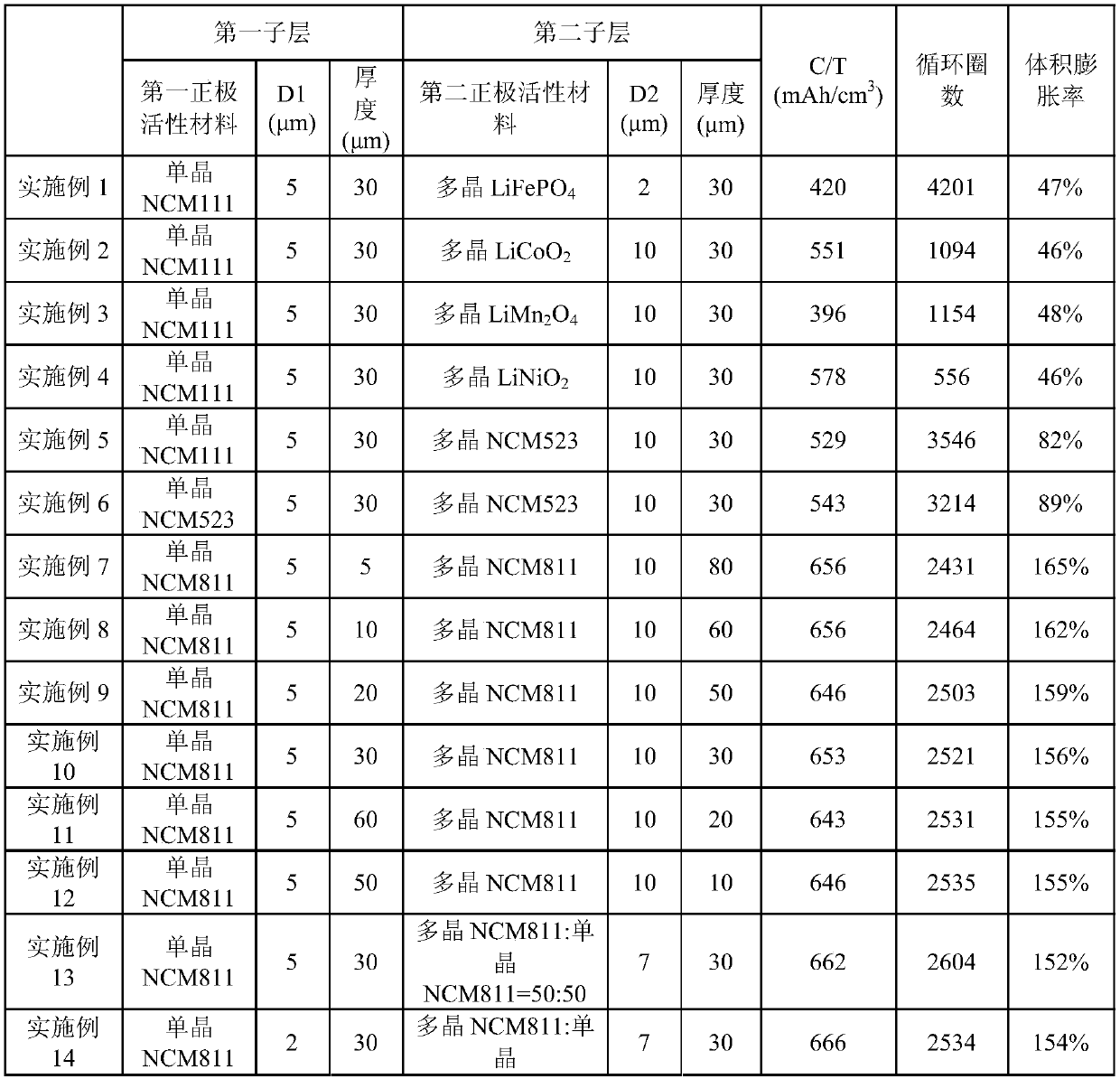
[0012] The positive electrode sheet according to the first aspect of the present application includes a positive electrode current collector and a positive electrode active material layer disposed on the positive electrode current collector. The positive electrode active material layer includes a first sublayer and a second sublayer, the first sublayer is located at the outermost layer of the positive electrode active material layer, and the second sublayer is located at the positive electrode current collector and the between the first sublayer. The first sublayer includes a first positive electrode active material, the second sublayer includes a second positive electrode active material, and the first positive electrode...


PUM

PropertyMeasurementUnit
particle sizeaaaaaaaaaa
particle diameteraaaaaaaaaa

Abstract

The invention provides a positive electrode plate and a lithium ion battery. The positive electrode plate comprises a positive current collector and a positive active material layer arranged on the positive current collector; the positive active material layer comprises a first sub-layer and a second sub-layer, wherein the first sub-layer is located on the outermost layer of the positive active material layer, and the second sub-layer is located between the positive current collector and the first sub-layer; the first sub-layer comprises a first positive electrode active material, the second sub-layer comprises a second positive electrode active material, and the first positive electrode active material is selected from one or more of a ternary positive electrode material with a single crystal or single crystal-like structure and a coating modification material of the ternary positive electrode material. The energy density of the lithium ion battery can be improved, and the gas production rate of the lithium ion battery can be reduced, so that the lithium ion battery has the advantages of high energy density and good storage performance.

Description

technical field [0001] The present application relates to the field of batteries, in particular to a positive electrode sheet and a lithium ion battery. Background technique [0002] In order to pursue high-energy-density lithium-ion batteries, the positive electrode sheet is usually required to have a high compaction density. Commonly used positive electrode active materials, such as ternary positive electrode materials, are secondary particles formed by the agglomeration of primary particles, and the primary particles inside the secondary particles The bonding force between them is not strong, so the secondary particles are easily crushed and broken under pressure during the cold pressing process of the positive electrode sheet, especially the positive electrode active material particles at the contact position between the surface of the positive electrode sheet and the cold pressing roller are very easy to break, and eventually Lead to the deterioration of gas production ...

Claims


Application Information

Patent Timeline
Patent Type & Authority Applications(China)
IPC IPC(8): H01M4/131H01M4/36H01M4/485H01M4/505H01M4/525H01M10/0525
CPCH01M4/131H01M4/366H01M4/485H01M4/505H01M4/525H01M10/0525H01M4/136H01M4/5825H01M2004/021Y02E60/10H01M2004/028
Inventor 杜锐柳娜闫传苗刘勇超
Owner CONTEMPORARY AMPEREX TECH CO
Why Eureka
Try Eureka