Graph arrangement method and system for naked eye 3D display effect optimization and electronic equipment

A technology for display effects and electronic equipment, applied in stereo systems, image communications, electrical components, etc., can solve problems such as poor stereo effects and poor experience, and achieve a good stereo effect.

Inactive Publication Date: 2020-01-07
SHENZHEN SUPER SMART AI TECH CO LTD
View PDF3 Cites 3 Cited by
  • Summary
  • Abstract
  • Description
  • Claims
  • Application Information

AI Technical Summary

Problems solved by technology

[0008] Aiming at the above technical problems, the present invention discloses a layout method, system and electronic equipment for optimizing naked-eye 3D display effect, which solves the problem of poor three-dimensional effect and poor experience in the edge areas of left and right images

Method used


Image

  • Graph arrangement method and system for naked eye 3D display effect optimization and electronic equipment
  • Graph arrangement method and system for naked eye 3D display effect optimization and electronic equipment
  • Graph arrangement method and system for naked eye 3D display effect optimization and electronic equipment

Examples


Embodiment 1

[0040] A method for arranging images with naked-eye 3D display effect optimization, comprising the following steps:

[0041] The first step is consistent with the conventional layout algorithm:

[0042] A. According to the specifications of the 2D display screen, the specifications of the grating, the distance of the placement distance, and the viewing distance that needs to be matched, that is, according to the initial optical design, calculate the matching on the 2D display device within each grating period, that is, within the Pitch The graph layout cycle, that is, the graph layout Pitch.

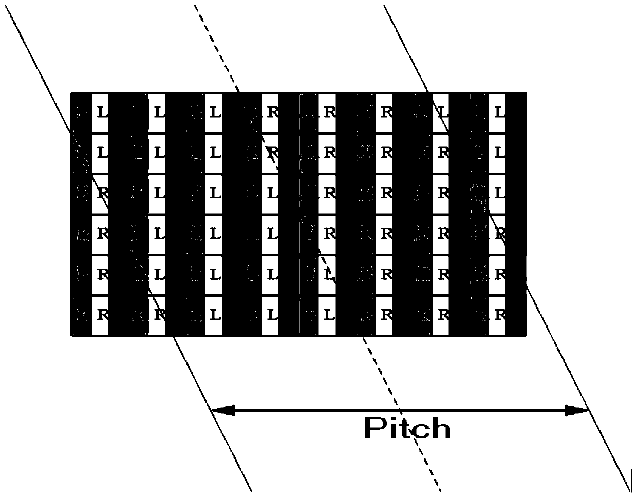
[0043] B. Next, according to the number of viewpoints, confirm whether each sub-pixel at each position in each layout Pitch corresponds to a left-eye image or a right-eye image. can refer to figure 1 , where 2 viewpoints are taken as an example to illustrate.

[0044] C. Then assign the brightness of each sub-pixel according to the corresponding left-eye image and right-eye image. As...

Embodiment 2

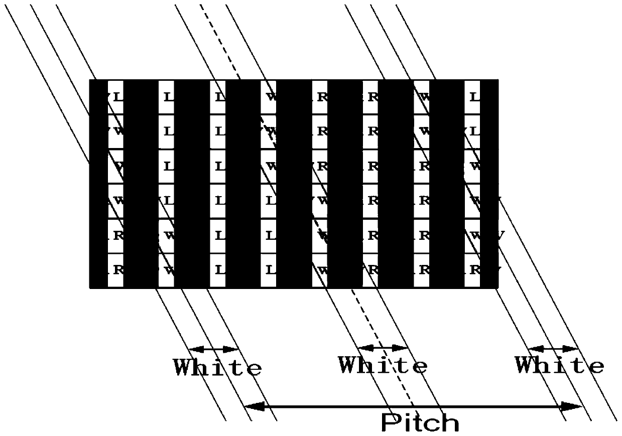
[0050] On the basis of Embodiment 1, the second step of this embodiment is different in that the white interpolation process is performed on the conversion area of ​​the left-eye image and the right-eye image, that is, the edge area, such as image 3 shown. The so-called white insertion processing is represented by W in this part of the figure. But W means that for the main pixel, for each sub-pixel: the single color with the highest value, that is, 255R (red sub-pixel); 255G (green sub-pixel); 255B (blue sub-pixel); three 255 Sub-pixels of different colors are superimposed to be 255 white, that is, pure white.

[0051] Further, while having an impact on the display resolution, the white interpolation part is no more than one main pixel, that is, three sub-pixels. Preferably, there is only one sub-pixel in the white-inserted part.

[0052] In addition, the gratings are all inclined, so the corresponding layout cycle, that is, Pitch is also inclined. For displays with differ...


PUM


Abstract

The invention provides a graph arrangement method and system for naked eye 3D display effect optimization and and electronic equipment, and the method comprises the steps: S1, carrying out display layout according to the pixel structure of a display screen, and obtaining a left-eye image and a right-eye image; and S2, performing black insertion or white insertion processing in a conversion regionof the left eye image and the right eye image. By adopting the technical scheme of the invention, crosstalk, dizziness and poor experience caused by incomplete light splitting or intersection of leftand right images in an edge area range can be avoided, so that a left eye and a right eye of a user are respectively provided with an image which is not received by the other corresponding eye; thatis to say, images without crosstalk are obtained, a better matched parallax error is obtained, and a good stereoscopic impression is achieved.

Description

technical field [0001] The invention belongs to the technical field of stereoscopic display, and in particular relates to a layout method, system and electronic equipment for optimizing naked-eye 3D display effect. Background technique [0002] The principle of 3D stereoscopic imaging is to make people's left and right eyes see two pictures of the same object but with different viewing angles. Using the principle of human's binocular parallax to form a stereoscopic image, a stereoscopic display effect is produced on a flat display medium. [0003] The principle of the existing naked-eye 3D display is generally to split the images displayed on the display through gratings such as slits or lenses, so that the human eyes receive different images, thus realizing 3D display. The layout algorithm of the 2D display that matches the grating is particularly critical. [0004] Existing gratings, that is, light splitting devices, have certain crosstalk, and cannot achieve 100% complet...

Claims


Application Information

Patent Timeline
Patent Type & Authority Applications(China)
IPC IPC(8): H04N13/122H04N13/302H04N13/383
CPCH04N13/122H04N13/302H04N13/383
Inventor 谭杰夫
Owner SHENZHEN SUPER SMART AI TECH CO LTD
Why Eureka
Try Eureka