Soybean seeding device

A sowing device, soybean technology, applied in the direction of sowing, planter parts, spaced quantitative sowing machinery, etc., can solve the problems of through hole blockage, seed damage, manual cleaning, etc.

Inactive Publication Date: 2020-01-10
田玉龙
View PDF7 Cites 3 Cited by
  • Summary
  • Abstract
  • Description
  • Claims
  • Application Information

AI Technical Summary

Problems solved by technology

[0004] 1. After the sowing is completed, there are residual seeds in the box for storing seeds, which needs to be cleaned manually
[0005] 2. The seeds are discharged through the pipe, and there are too many seeds at the entrance of the pipe to block the through hole
[0006] 3. There is a phenomenon that the seed is damaged when the discharge of the seed cannot be controlled or the discharge of the seed is controlled
[0007] 4. The seeds are discharged at the same speed and cannot be discharged intermittently
[0008] 5. The soil is covered completely, and there is a phenomenon of bare seeds

Method used


Image

  • Soybean seeding device
  • Soybean seeding device
  • Soybean seeding device

Examples


specific Embodiment approach 1

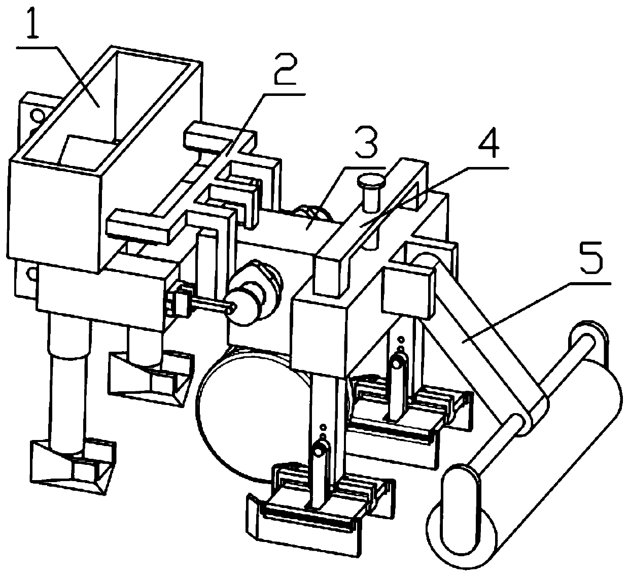
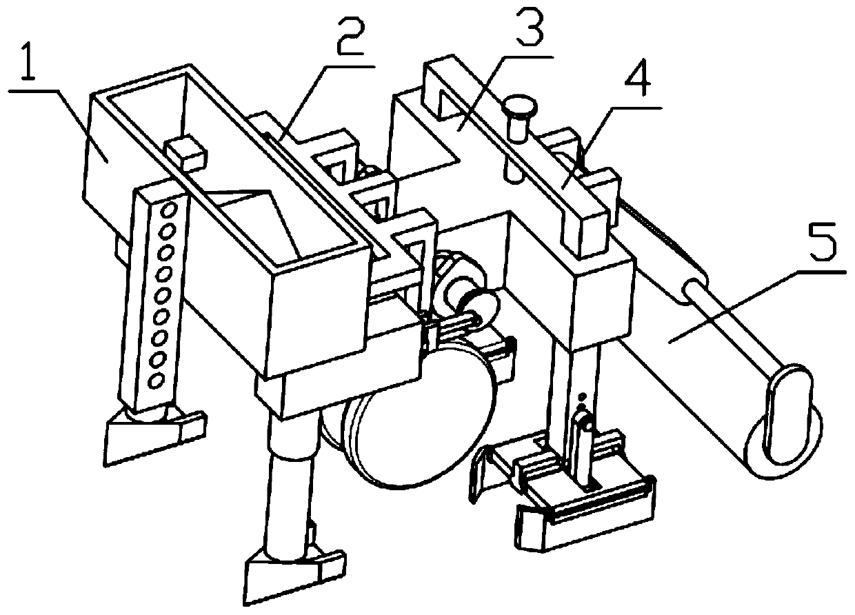
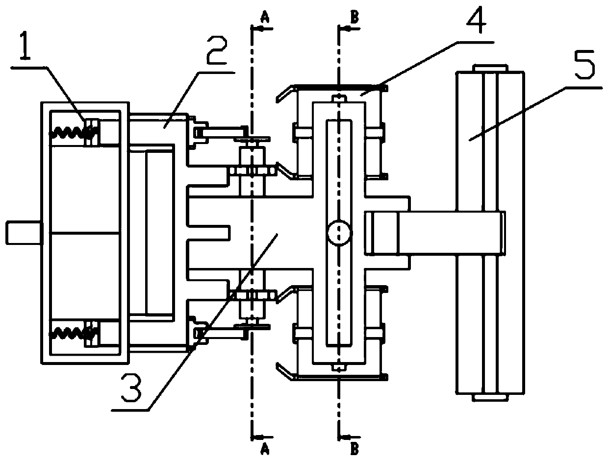
[0047] Combine below Figure 1-19 Description of this embodiment, a soybean sowing device, including a material storage and discharge mechanism 1, a discharge control mechanism 2, a connecting housing 3, a closing mechanism 4 and a compacting mechanism 5, and the discharge control mechanism 2 is movably installed on the In the groove provided on the material storage and discharge mechanism 1, the discharge control mechanism 2 is installed in the inner groove provided on the connecting shell 3, and the closing mechanism 4 is movably installed on the through hole provided on the connecting shell 3, compacting The mechanism 5 is movably installed on the connection housing 3 .

specific Embodiment approach 2

[0049] Combine below Figure 1-19 Describe this embodiment, this embodiment will further explain the first embodiment, the storage and discharge mechanism 1 includes a storage box 1-1, a power connection plate 1-2, a diverter block 1-3, a middle square column 1- 4. The inner threaded pipe 1-5, the outer threaded pipe 1-6, the ditching piece 1-7, the power connection plate 1-2 are fixedly installed on one side of the material storage box 1-1, and the diverter block 1-3 is fixedly installed on the Inside the material storage box 1-1, two through holes are arranged on the bottom plate inside the material storage box 1-1, the diverter block 1-3 is located between the two through holes, and the number of the middle square column 1-4 has two One, the middle square column 1-4 is fixedly installed on the material storage box 1-1, respectively located at the two ends of the material storage box 1-1, there are two internal threaded pipes 1-5, and the internal threaded pipes 1-5 Fixedly...

specific Embodiment approach 3

[0051] Combine below Figure 1-19 Describe this embodiment, this embodiment will further explain the second embodiment, the discharge control mechanism 2 includes a toggle frame 2-1, a material control assembly 2-2, a multifunctional shaft 2-3, and a driving wheel 2- 4. The toggle frame 2-1 is in contact with the multifunctional shaft 2-3. There are two material control components 2-2, which are respectively installed on both sides of the multifunctional shaft 2-3. The material control component 2-2 It is movably installed on the multifunctional shaft 2-3, the drive wheel 2-4 is installed on the multifunctional shaft 2-3, and the material control assembly 2-2 is movably installed on the groove provided on the middle square column 1-4; Frame 2-1 comprises toggle top frame 2-1-1, toggle pin 2-1-2, baffle plate 2-1-3, slider 2-1-4, support spring 2-1-5, support spring One end of 2-1-5 is fixedly installed on the top frame 2-1-1, and the other end is fixedly installed on the mate...


PUM


Abstract

The invention relates to an agricultural seeding device, in particular to a soybean seeding device. The soybean seeding device comprises a material storage and discharging mechanism, a discharging control mechanism, a connection shell, a closing mechanism and a compacting mechanism. The soybean seeding device has advantages that seed damage is avoided, seeds can be discharged completely without residues, continuous seed discharging and intermittent seed discharging can be both realized, and a soil closing function, an adjustment function and a soil compacting function are achieved. The discharging control mechanism is movably mounted in a groove of the material storage and discharging mechanism and positioned in an inner groove of the connection shell; the closing mechanism is movably mounted in through holes of the connection shell; the compacting mechanism is movably mounted on the connection shell.

Description

technical field [0001] The invention relates to an agricultural seeding device, in particular to a soybean seeding device. Background technique [0002] Soybean planting in mountainous areas cannot be sown by large-scale agricultural machinery, and manual sowing is inefficient, requires a lot of labor, and often requires small-scale sowing machinery, and the existing small-scale sowing machinery has many disadvantages. [0003] The disadvantages are as follows: [0004] 1. After the sowing is completed, there are residual seeds in the box for storing seeds, which needs to be cleaned manually. [0005] 2. The seeds are discharged through the pipeline, and there are too many seeds at the entrance of the pipeline to block the through hole. [0006] 3. There is a phenomenon that the seed is damaged when the discharge of the seed cannot be controlled or the discharge of the seed is controlled. [0007] 4. The seeds are discharged at the same speed and cannot be discharged inte...

Claims


Application Information

Patent Timeline
Patent Type & Authority Applications(China)
IPC IPC(8): A01C5/06A01C7/00A01C7/18A01C7/20
CPCA01C5/062A01C5/068A01C7/00A01C7/18A01C7/20
Inventor 田玉龙
Owner 田玉龙
Why Eureka
Try Eureka