
Detector module, detector, and medical imaging device

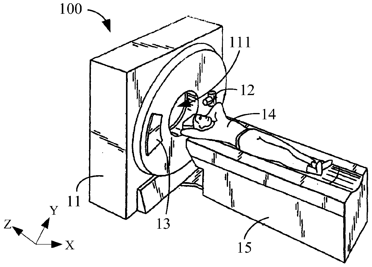
A detector and sub-module technology, used in instruments, measuring devices, scientific instruments, etc., can solve problems such as incomplete inspection range, affecting diagnosis results, and affecting the acquisition of complete images of scanned parts, and achieve the effect of improving accuracy

Pending Publication Date: 2020-01-10
NEUSOFT MEDICAL SYST CO LTD
View PDF16 Cites 8 Cited by
  • Summary
  • Abstract
  • Description
  • Claims
  • Application Information

AI Technical Summary

Problems solved by technology

[0003] However, in the existing detectors, due to the limitation of the functional modules in each detector sub-module, there is a large gap between the detection devices of the adjacent detector sub-modules in the detector, so that continuous scanning data cannot be formed at the scanning position, and the Continuous scanning data will result in incomplete inspection range, which will affect the complete image of the scanning part, thus affecting the diagnosis result

Method used


Image

  • Detector module, detector, and medical imaging device
  • Detector module, detector, and medical imaging device
  • Detector module, detector, and medical imaging device

Examples


Embodiment Construction

[0034] The application will be described in detail below in conjunction with specific implementations shown in the accompanying drawings. However, these implementations do not limit the present application, and any structural, method, or functional changes made by those skilled in the art based on these implementations are included in the protection scope of the present application.

[0035] The terminology used in this application is for the purpose of describing particular embodiments only, and is not intended to limit the application. As used in this application and the appended claims, the singular forms "a", "the", and "the" are intended to include the plural forms as well, unless the context clearly dictates otherwise. It should also be understood that the term "and / or" as used herein refers to and includes any and all possible combinations of one or more of the associated listed items.

[0036] Some implementations of the present application will be described in detail...


PUM


Abstract

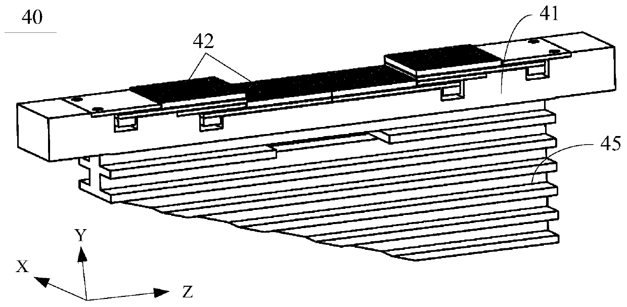
The invention relates to a detector module, a detector and a medical imaging device. The detector module comprises a module support and a plurality of detector sub-modules arranged on the module support in an extending direction of the module support. In the extending direction of the module support, each detector sub-module comprises a first area provided with a detector device and a second areaprovided with a functional module, and the functional modules are electrically connected with the detector device and used for receiving electric signals of the detector device; wherein the first areaof at least one detector sub-module in the plurality of detector sub-modules is at least partially stacked in the second area of the other detector sub-module. According to the invention, the first area with the detection function in the detector sub-module is stacked in the non-detection second area so as to reduce or eliminate a gap in the detector module, thereby the detailed scanning data isformed at a scanning part, and the precision of a diagnosis result is improved.

Description

technical field [0001] The present application relates to the technical field of medical equipment, in particular to a detector module, a detector and medical imaging equipment. Background technique [0002] With the continuous development of medical level, more and more medical devices are used to assist medical diagnosis or treatment. For example, CT (Computed Tomography, computerized tomography) equipment is used to detect human diseases. CT equipment detects X-rays passing through the human body through CT detectors, and converts the received light signals into electrical signals. [0003] However, in the existing detectors, due to the limitation of the functional modules in each detector sub-module, there is a large gap between the detection devices of the adjacent detector sub-modules in the detector, so that continuous scanning data cannot be formed at the scanning position, and the Continuous scan data will result in incomplete inspection range, which will affect t...

Claims


Application Information

Patent Timeline
Patent Type & Authority Applications(China)
IPC IPC(8): A61B6/03A61B6/00
CPCA61B6/035A61B6/4291A61B6/4488A61B6/4266G01T1/2985G01T1/20182A61B6/032G01T1/20181A61B6/4283A61B6/4435
Inventor 于军李双学谭益广
Owner NEUSOFT MEDICAL SYST CO LTD
Learn More