Leg walking control system of bionic robot

A bionic robot, walking control technology, applied in the field of robotics, to achieve the effect of low latency

Active Publication Date: 2020-01-10
路邦科技授权有限公司
View PDF5 Cites 0 Cited by
  • Summary
  • Abstract
  • Description
  • Claims
  • Application Information

AI Technical Summary

Problems solved by technology

From 1968 to 1969 , the famous Yugoslavian scientist M.Vukobratovic proposed an important theory for studying biped robots, that is, the  MP stability  criterion, and dev

Method used


Image

  • Leg walking control system of bionic robot
  • Leg walking control system of bionic robot
  • Leg walking control system of bionic robot

Examples


Embodiment Construction

[0038] The present invention will be further described below in conjunction with the accompanying drawings and embodiments.

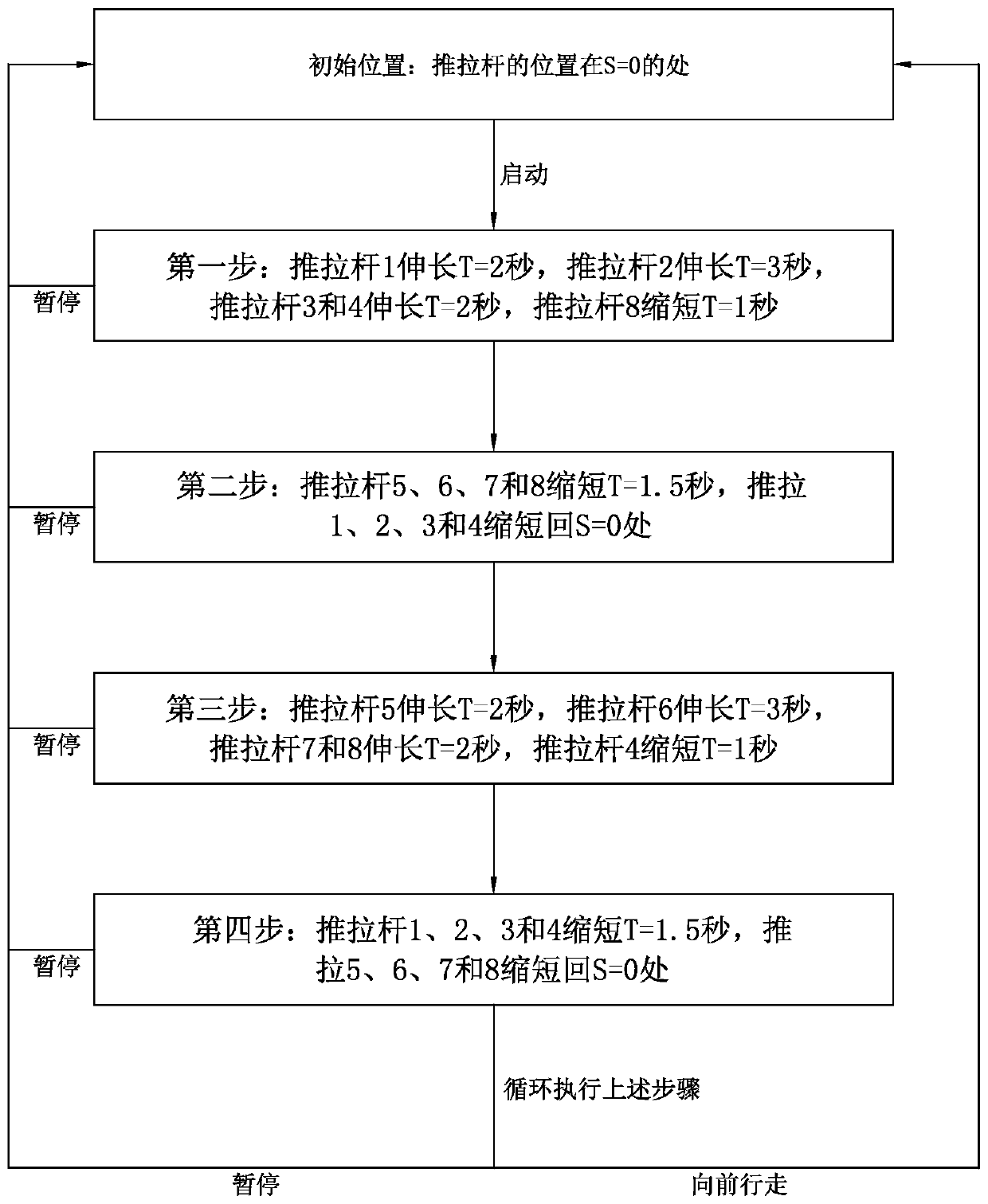
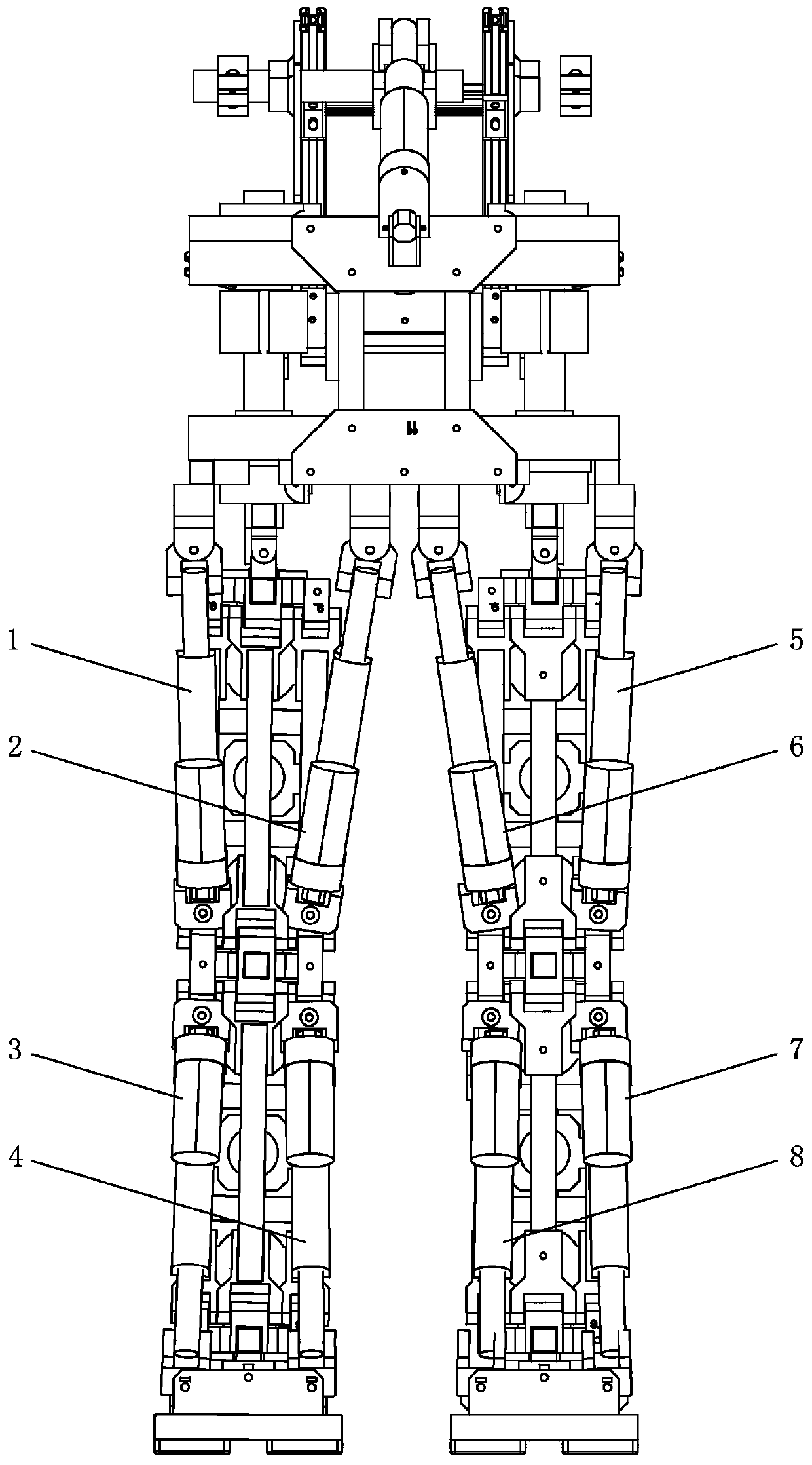
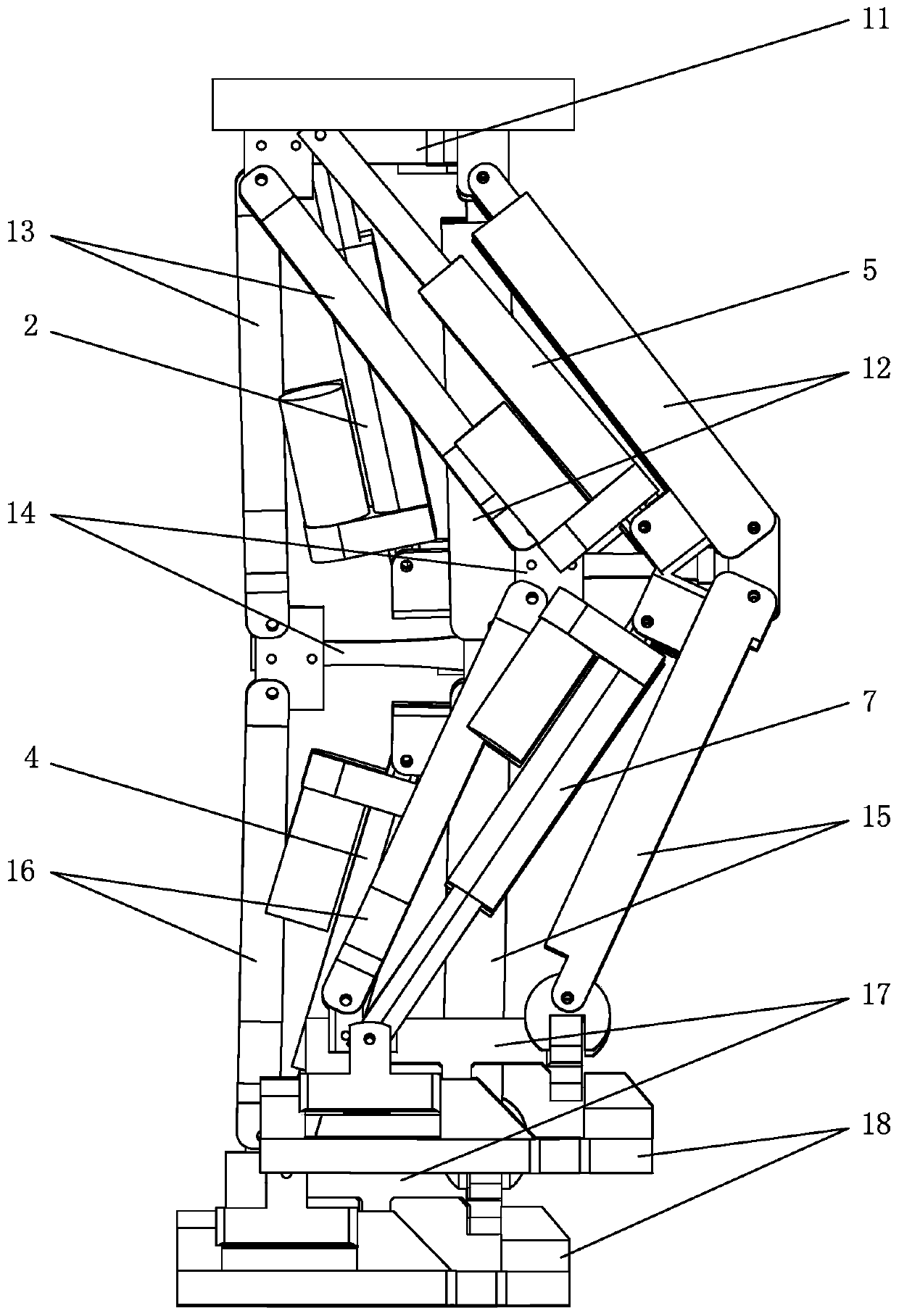
[0039] see Figure 1-Figure 3 , in the leg walking control system of the bionic robot, the bionic robot involved includes the first leg assembly (left side) and the second leg assembly (right side); the first leg assembly includes the thigh assembly located in The first thigh push-pull rod 1 on the outside, the second thigh push-pull rod 2 positioned on the inside in the thigh assembly, the first calf push-pull rod 3 positioned on the outside in the calf assembly, and the second calf push-pull rod 4 positioned on the inside in the calf assembly; The second leg assembly includes the third thigh push-pull rod 5 positioned at the outside in the thigh assembly, the fourth thigh push-pull rod 6 positioned at the inside in the thigh assembly, the third calf push-pull rod 7 positioned at the outside in the calf assembly, and the third calf push-pull rod 7 posi...


PUM


Abstract

The invention relates to a leg walking control system of a bionic robot. The leg walking control system comprises the following steps that firstly, a first leg assembly lifts a corresponding leg, anda second leg assembly stands; secondly, the first leg assembly recovers to stand, and the second leg assembly pushes back; thirdly, the first leg assembly remains standing, and the second leg assemblylifts a corresponding leg; and fourthly, the second leg assembly recovers to stand, the first leg assembly pushes back, and the steps are circularly executed. The leg walking control system of the bionic robot can enable the legs of the bionic robot to imitate the posture similar to human walking, so that the bionic robot keeps balance and can walk forward stably, and the moving range is wider.

Description

technical field [0001] The invention relates to the field of robots, in particular to a leg walking control system of a bionic robot. Background technique [0002] The research on biped walking robot began in 1968. R. Smo- sher of General Motors of the United States trial-produced a manipulative biped walking robot named "Rig", which opened the prelude to the biped robot research, but the robot There are only two joints, ankle and hip, and the operator relies on force feedback to maintain the balance of the robot. From 1968 to 1969 , the famous Yugoslavian scientist M.Vukobratovic proposed an important theory for studying biped robots, that is, the  MP stability  criterion, and developed the world’s first real biped robot; A biped walking robot controlled by programming cannot handle many critical situations by programmed control alone. [0003] Therefore, further improvements are required. Contents of the invention [0004] The purpose of the present invention is to ov...

Claims


Application Information

Patent Timeline
IPC IPC(8): B62D57/032
CPCB62D57/032
Inventor 麦骞誉
Owner 路邦科技授权有限公司
Why Eureka
Try Eureka