Marine Cargo Lifting Device

A lifting device and cargo technology, which is applied in the direction of lifting devices, cargo, cargo handling equipment, etc., can solve the problems of affecting the efficiency of cargo transfer in boxes, shaking of the ship hull, and increasing labor costs, so as to achieve easy and convenient lifting and transfer, and prevent breakage , Improve the effect of impact resistance

Active Publication Date: 2020-11-13
ANQING MARINE ELECTRIC DEVICE
View PDF5 Cites 0 Cited by
  • Summary
  • Abstract
  • Description
  • Claims
  • Application Information

AI Technical Summary

Problems solved by technology

The appearance is generally a streamlined envelope that is conducive to overcoming fluid resistance. The materials are constantly updated with the advancement of science and technology. In the early days, they were natural materials such as wood, bamboo, and hemp. In modern times, they are mostly steel, aluminum, glass fiber, acrylic and various composite materials; The existing cargo lifting device used on the hull often binds the cargo first when it is in use, and when it needs to be removed when it is raised to a suitable height, the tied rope needs to be removed. The purpose of doing this is to During sea travel, wind and waves can easily cause the hull to shake, but repeated disassembly and assembly greatly increase labor costs and affect the efficiency of cargo transfer in boxes. Therefore, we propose a cargo lifting device that does not need to fasten the cargo

Method used


Image

  • Marine Cargo Lifting Device
  • Marine Cargo Lifting Device
  • Marine Cargo Lifting Device

Examples


Embodiment 1

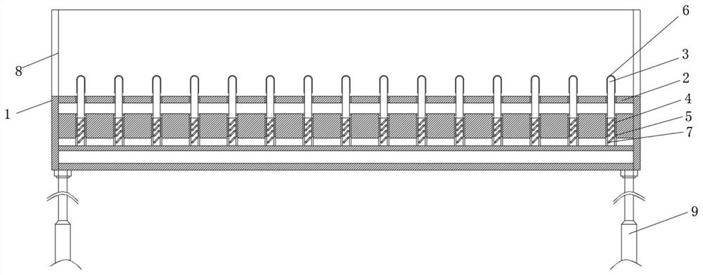
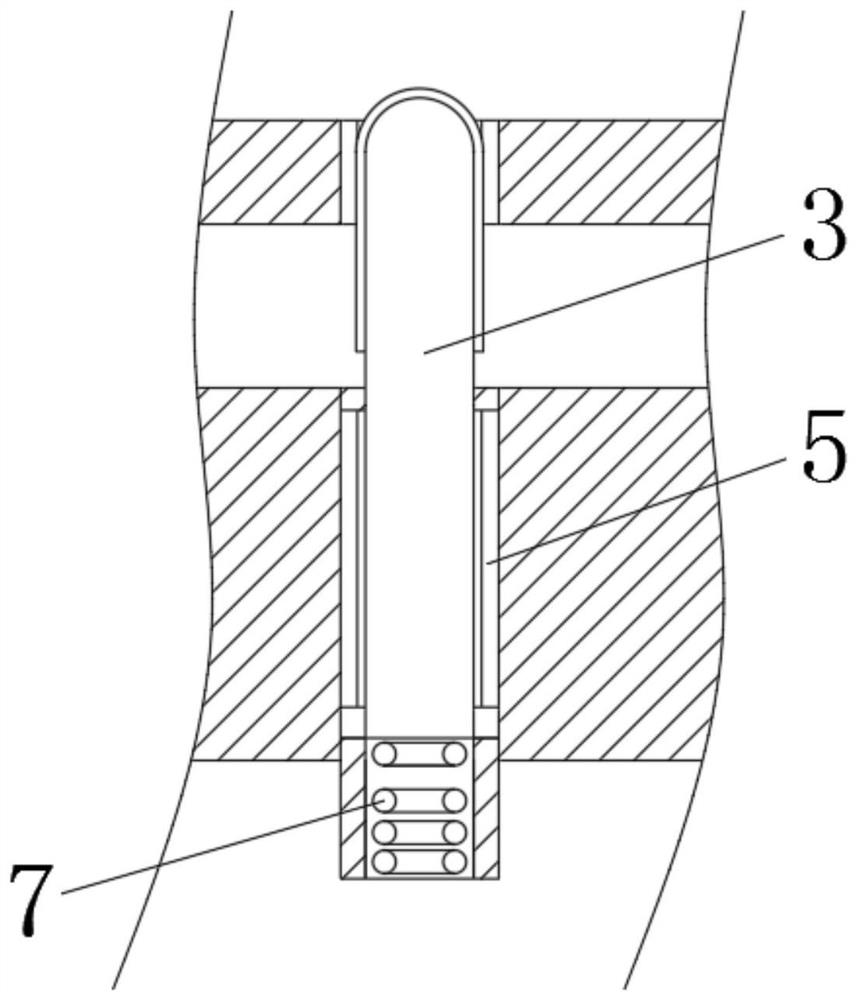
[0021] Such as Figure 1-2 As shown, the marine cargo lifting device includes a lifting rod 9, a lifting plate 1 is fixedly installed on the outer surface of the upper end of the lifting rod 9, and a guardrail 8 is fixedly installed on the outer surface of the upper end of the lifting plate 1 near the surroundings. The outer surface of the upper end of the lifting plate 1 is provided with a moving hole 4, and the inner wall surface of the moving hole 4 is provided with a limit moving groove 5, and a limiting column 3 is arranged in the moving hole 4, and the outer surface of the limiting column 3 A limiting moving block is provided, the limiting moving block moves up and down in the limiting moving groove 5, the limiting column 3 is limited to moving up and down in the moving hole 4, and the outer surface of the lower end of the limiting column 3 is fixedly connected with a compression spring 7 The outer surface of the upper end of the lifting plate 1 is also laid with an elas...

Embodiment 2

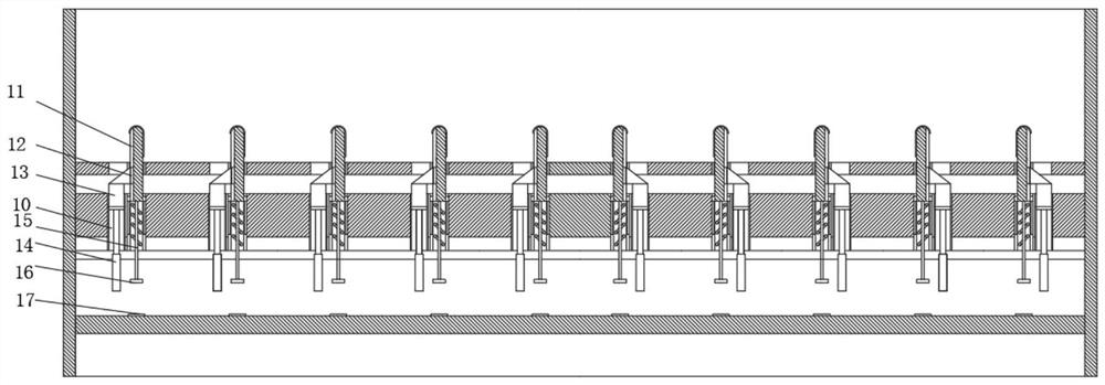
[0024] On the basis of above-mentioned embodiment 1, in order to further improve the stability of this device, make further improvement, as Figure 3-5 As shown, the outer surface of the upper end of the lifting plate 1 is provided with a lifting and moving groove 10, and the outer surface of the limiting column 3 and the lifting and moving groove 10 are provided with a chute 11, and a limiting block is arranged in the chute 11 12. The lower end of the limiting block 12 is fixedly connected with a resisting block 13, and the outer surface of the lower end of the resisting block 13 is fixedly connected with a telescopic rod 14, and the resisting block 13 moves in the lifting and moving groove 10 through the telescopic rod 14, and resists Block 13 is structured as image 3 As shown; one group of said restricting column 3 is provided with two groups of adjacent chute 11, and each group of said chute 11 is provided with a restricting block 12; also includes a control machine, the ...


PUM


Abstract

The invention relates to a marine cargo lifting device. The marine cargo lifting device includes a lifting rod. A lifting plate is fixedly installed on the outer surface of the upper end of the lifting rod. There is a movement hole on the surface, the inner wall surface of the movement hole is provided with a limit movement groove, the movement hole is provided with a limit column, and the outer surface of the limit column is provided with a limit movement block, and the limit movement block is located at the limit position. Move up and down in the moving tank; the marine cargo lifting device is easy to use and easy to operate, saving the time for fixing and disassembling the cargo, making it easier for workers to lift and transfer the cargo, and easy to promote and use.

Description

technical field [0001] The invention belongs to the technical field of marine lifting devices, and in particular relates to a marine cargo lifting device. Background technique [0002] A ship is a man-made means of transportation that primarily operates in geographical waters. In addition, civilian ships are generally called ships, military ships are called ships, and small ships are called boats or boats, which are collectively called ships or boats. The interior mainly includes accommodation space, support structure and drainage structure, and has a propulsion system that utilizes external or self-contained energy. The appearance is generally a streamlined envelope that is conducive to overcoming fluid resistance. The materials are constantly updated with the advancement of science and technology. In the early days, they were natural materials such as wood, bamboo, and hemp. In modern times, they are mostly steel, aluminum, glass fiber, acrylic and various composite mater...

Claims


Application Information

Patent Timeline
Patent Type & Authority Patents(China)
IPC IPC(8): B66F7/28B63B25/24B63B27/16
CPCB63B25/004B63B25/24B63B27/16B66F7/28
Inventor 王良恩
Owner ANQING MARINE ELECTRIC DEVICE
Why Eureka
Try Eureka