Coupler for shaft suspending type installing direct drive motor and rigid design method thereof

A direct-drive motor and coupling technology, which is applied in the direction of couplings, elastic couplings, mechanical equipment, etc., can solve the problem that the connection structure on the motor side and the connection structure on the axle side cannot be centered and positioned, and the rubber blocks are difficult to install in place at the same time , Increase the failure risk of the motor system, etc., to improve the installation reliability and convenience, reduce the failure risk, and facilitate maintenance and replacement

Active Publication Date: 2020-01-10
ZHUZHOU TIMES NEW MATERIALS TECH
View PDF5 Cites 5 Cited by
  • Summary
  • Abstract
  • Description
  • Claims
  • Application Information

AI Technical Summary

Problems solved by technology

[0003] In the above patents, the radial load is all sheared by the wedge-shaped rubber block, and its radial load-bearing capacity is insufficient, the rubber block is easily damaged, and the service life is short
And long-term heavy loads will cause the rubber block to creep, increasing the risk of failure of the motor system; In addition, the motor side connection structure and the axle side connection structure of the above patents cannot be aligned, and because the rubber block needs to be pre-pressed and installed, the elastic ring It is difficult to install each rubber block in place at the same time, and it needs to be installed with the help of complicated special fixtures, which is extremely inconvenient for installation and maintenance.

Method used


Image

  • Coupler for shaft suspending type installing direct drive motor and rigid design method thereof
  • Coupler for shaft suspending type installing direct drive motor and rigid design method thereof
  • Coupler for shaft suspending type installing direct drive motor and rigid design method thereof

Examples


Embodiment Construction

[0028] Combine below Figure 1 to Figure 7 Embodiments of the present invention are described in detail.

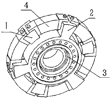
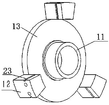
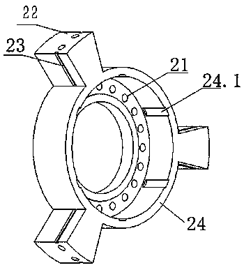
[0029] A shaft-suspended shaft coupling for a direct-drive motor, including a hub-side connection plate 1 coaxially fixed with the wheel shaft and a motor-side connection plate 2 coaxially fixed with the motor rotor shaft, characterized in that it also includes an elastically supported rotating assembly 3, The elastic support rotating assembly 3 is connected radially between the axle side connecting plate 1 and the motor side connecting plate 2, so that the wheel axle side connecting plate 1 and the motor side connecting plate 2 are coaxially rotatable connected, and the rotating assembly is supported by elastic support. 3 Carry the weight of the motor in the radial direction, and the connection plate 1 on the wheel shaft side and the connection plate 2 on the motor side are elastically connected in the circumferential direction.

[0030] In the present invention, the co...


PUM


Abstract

The invention provides a coupler for a shaft suspending type installing direct drive motor. The coupler comprises an axle side connecting disc fixed coaxially with an axle, and a motor side connectingdisc fixed coaxially with a motor rotor shaft. The coupler is characterized by further comprising an elastic supporting rotating assembly. The elastic supporting rotating assembly is connected between the axle side connecting disc and the motor side connecting disc, thus the axle side connecting disc and the motor side connecting disc are coaxially connected in a rotating manner, the elastic supporting rotating assembly bears the motor weight in the radial direction, and the axle side connecting disc and the motor side connecting disc are elastically connected in the peripheral direction. According to the coupler, while the requirement for large radial load is met, the better vibration reducing and buffering effect can be obtained, the failure risk is reduced, the service life of a metalrubber part is prolonged, the use reliability of the coupler is improved, centering connection between the axle side connecting disc and the motor side connecting disc can be achieved easily, the installing reliability and convenience of the coupler are improved, the installing process is convenient and easy, and overhauling and replacing are facilitated. The invention further provides a rigiditydesign method of the coupler for the shaft suspending type installing direct drive motor.

Description

technical field [0001] The invention relates to a shaft coupling for a shaft-suspension mounted direct-drive motor and a stiffness design method thereof, belonging to the technical field of shaft couplings. Background technique [0002] The power bogie of a rail transit vehicle is mainly powered by a traction motor to realize wheel rolling motion. In order to meet the requirements of miniaturization and high transmission efficiency of the next-generation rail vehicle power bogie, the traction motor direct drive transmission system has become a research hotspot for major companies and research institutions. This system removes the gear box and other transmission devices, and the traction motor will be directly connected to the wheel shaft for driving, which has the advantages of high transmission efficiency, less maintenance, and low noise, but at the same time, the motor also needs to withstand the integrated wheel shaft. Larger magnitude vibration shock. In order to reduc...

Claims


Application Information

Patent Timeline
Patent Type & Authority Applications(China)
IPC IPC(8): F16D3/12H02K7/00B61C9/38
CPCF16D3/12H02K7/003B61C9/38H02K9/06H02K1/276B61C9/50F16D3/68F16C27/066H02K5/24H02K7/006
Inventor 肖光辉贺才春涂奉臣李昊
Owner ZHUZHOU TIMES NEW MATERIALS TECH
Why Eureka
Try Eureka