Intracavity internal feedback throttling liquid static electric spindle

An internal feedback, electro-spindle technology, applied in metal processing equipment, metal processing mechanical parts, manufacturing tools, etc., can solve the hidden trouble of throttling failure, the impact of throttling response speed, unstable performance and other problems, and achieve the internal flow of pressure oil. And the effect of small turbulence problem, stable throttling feedback performance and uniform heating temperature distribution

Active Publication Date: 2019-04-26
GUANGZHOU HAOZHI ELECTROMECHANICAL
View PDF6 Cites 2 Cited by
  • Summary
  • Abstract
  • Description
  • Claims
  • Application Information

AI Technical Summary

Problems solved by technology

[0008] Thin-film feedback throttling: Its advantage is that the shaft can obtain greater oil film stiffness under low oil inlet pressure and large clearance. The disadvantage is that it has high requirements on the characteristics of the film material and manufacturing process, and the consistency of the film restrictor is difficult. Guaranteed, as soon as the manufactured restrictor deviates from the actual range, the stiffness characteristics of the bearing will be greatly reduced
[0009] Spool valve feedback throttling: Its advantage is that it can adapt to the working conditions with large load changes. The disadvantage is similar to that of film feedback. At the same time, there is a throttle that is too large in size and needs to be connected to the outside through the oil circuit, and the throttle response speed is easily affected.
[0010] Compared with film feedback throttling and spool valve feedback throttling, internal feedback throttling has a simpler structure, faster response and better rigidity; however, internal feedback throttling in current engineering applications has its throttling link located outside the oil chamber , such an external throttling form increases the span of the main shaft, making it difficult to optimize the rigidity of the shafting system; it increases the friction area of ​​the liquid and generates a large amount of heat, and it is easy to cause the shaft to be locked due to the temperature rise; due to the large fuel consumption , the corresponding pump power consumption is also relatively large, and at the same time, a large amount of oil is likely to cause leakage and difficult sealing problems
[0011] In order to overcome the above-mentioned defects of feedback throttling inside and outside the cavity, someone proposed a three-row slot type oil cavity internal feedback throttling hydrostatic bearing structure, but this structure has the following obvious defects: hidden danger of throttling failure: due to the same oil cavity There is no secondary throttling link between the oil chamber of the oil tank and the working oil chamber, and the oil hydraulic pressure difference between the two oil chambers is very large, which easily leads to direct oil leakage, and the fluid state such as internal flow of pressure oil and turbulent flow is complicated, which brings Hydraulic oil leakage or even throttling failure hidden dangers
Unstable performance: The design requirements of the throttling parameters of this structure vary with the layout of the oil circuit, and there are many arrangements and combinations of the oil circuit layout, and the actual performance differences brought about by different oil circuit layouts are very large; the processing is difficult: According to the design theory of hydrostatic bearings, the hydrostatic bearing adopting the throttling method of three rows of grooves objectively requires a narrow throttling edge width to achieve reasonable rigidity, but narrow throttling edges are difficult to guarantee in actual processing, even if inverted Inconsistent angle sizes will also lead to great differences in throttling effects, so it is difficult to realize in actual processing, so it is difficult to apply and popularize in actual engineering

Method used


Image

  • Intracavity internal feedback throttling liquid static electric spindle
  • Intracavity internal feedback throttling liquid static electric spindle
  • Intracavity internal feedback throttling liquid static electric spindle

Examples


Embodiment Construction

[0035] Below, the present invention will be further described in conjunction with the accompanying drawings and specific implementation methods. It should be noted that, under the premise of not conflicting, the various embodiments described below or the technical features can be combined arbitrarily to form new embodiments. .

[0036] In describing the present invention, it is to be understood that the terms "upper", "lower", "front", "rear", "left", "right", "horizontal", "vertical", "top", The orientation or positional relationship indicated by "inner", "outer", etc. is based on the orientation or positional relationship shown in the drawings, and is only for the convenience of describing the present invention and simplifying the description, rather than indicating or implying that the referred device or element must have Certain orientations, constructed and operative in certain orientations, therefore are not to be construed as limitations of the invention. In addition, ...


PUM


Abstract

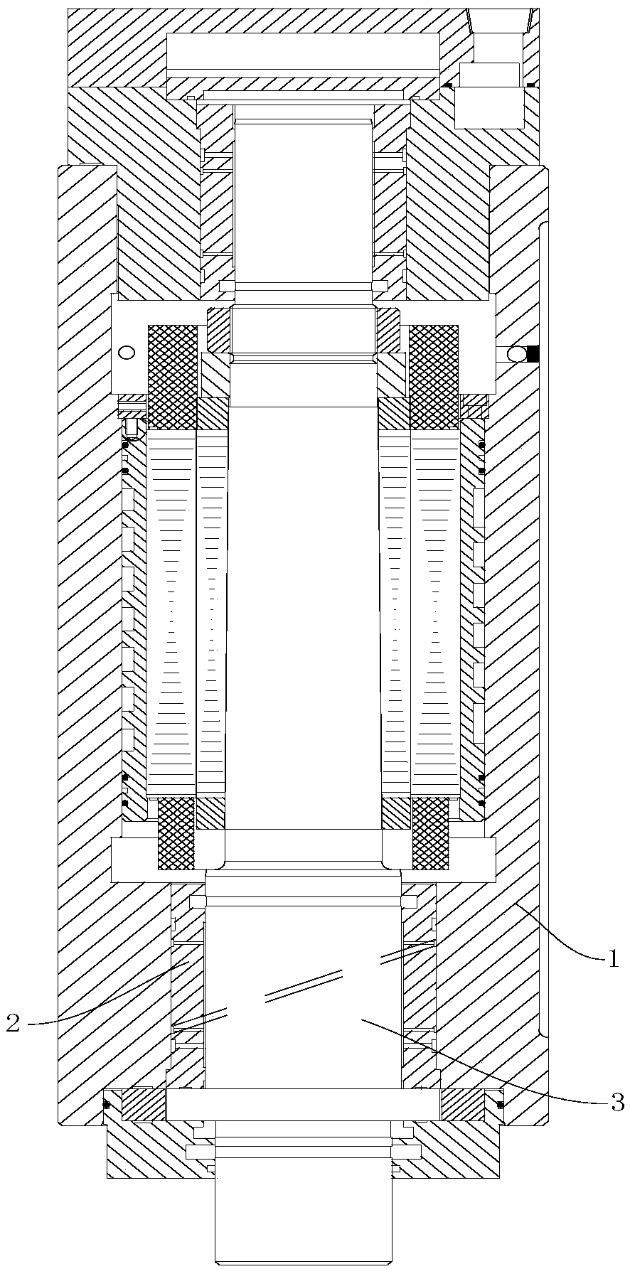
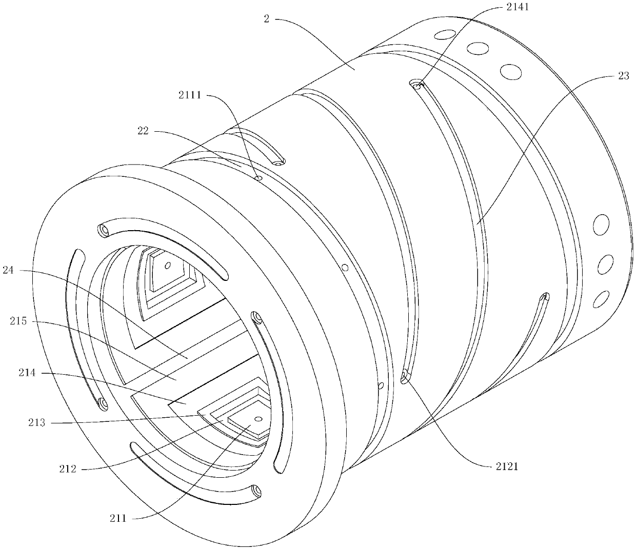
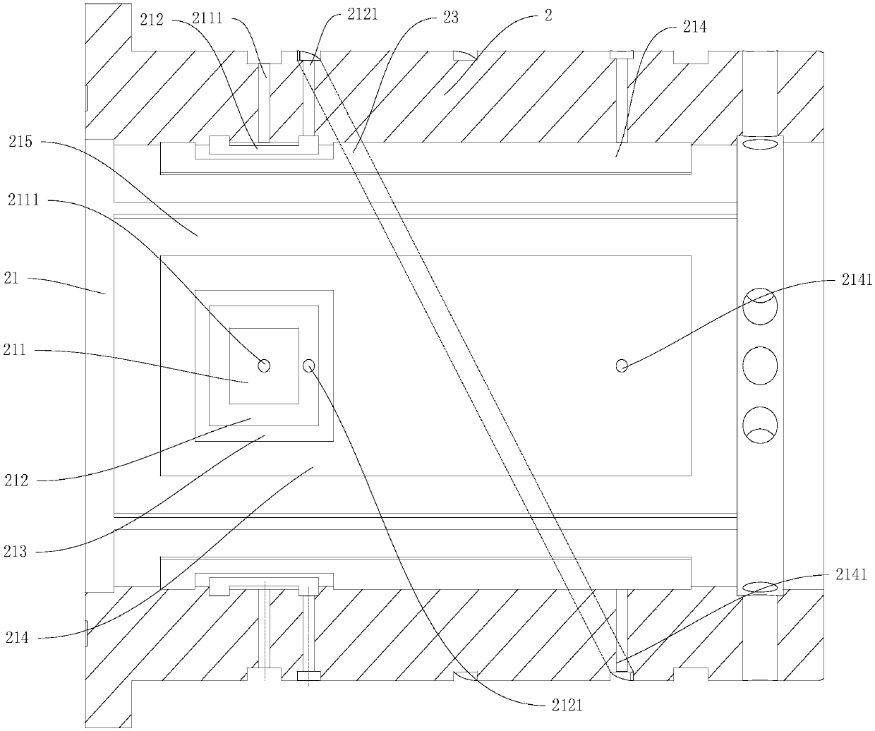
The invention discloses an intracavity internal feedback throttling liquid static electric spindle. The intracavity internal feedback throttling liquid static electric spindle comprises a machine body, a liquid static bearing and a rotary shaft. The rotary shaft is in rotary fit into the machine body through the liquid static bearing, an even number of throttlers are arranged on the inner wall face of the liquid static bearing, and every two throttlers are oppositely arranged. Each throttler comprises a throttling boss, an oil collecting oil cavity and a working oil cavity. The throttling bosses communicate with oil inflow branches outside the liquid static bearing, the oil collecting oil cavities surround the throttling bosses, the working oil cavities surround the oil collecting oil cavities, the working oil cavities are separated from the oil collecting oil cavities through first oil sealing flanges, and the oil collecting oil cavity of one of every two opposite throttlers communicates with the working oil cavity of the other one of every two opposite throttlers. By means of the intracavity internal feedback throttling liquid static electric spindle, effective throttling, stableperformance and easier machining can be guaranteed, and then the rigidity of the rotary shaft is improved.

Description

technical field [0001] The invention relates to the technical field of electric spindles, in particular to a feedback throttling hydrostatic electric spindle in a cavity. Background technique [0002] Machine tool spindle is the core functional component of modern machine tools, its function is to drive the tool (grinding wheel) or workpiece to rotate, and realize high-speed precision machining. The hydrodynamic and static piezoelectric spindle is a new type of machine tool spindle functional component that is supported by a hydrostatic bearing and integrates the functions of the machine tool spindle and the motor from the structure. [0003] With the continuous improvement of modern industry's requirements for machining accuracy and machining efficiency of machine tools, machine tools have higher and higher requirements for spindle performance. Compared with the traditional belt drive spindle, the hydrostatic electric spindle saves the complicated intermediate transmission...

Claims


Application Information

Patent Timeline
Patent Type & Authority Applications(China)
IPC IPC(8): B24B41/04B23B19/02
CPCB23Q1/70B24B41/04
Inventor 卜霞汤秀清熊万里郑良钢叶颖赵倩妮
Owner GUANGZHOU HAOZHI ELECTROMECHANICAL
Why Eureka
Try Eureka