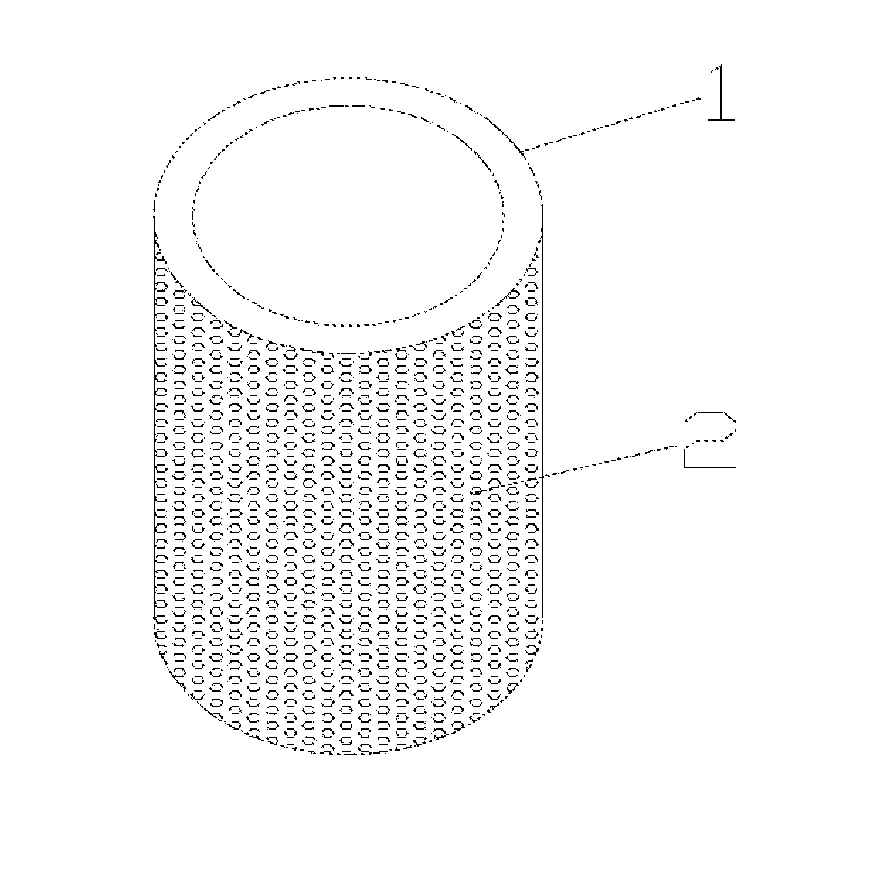
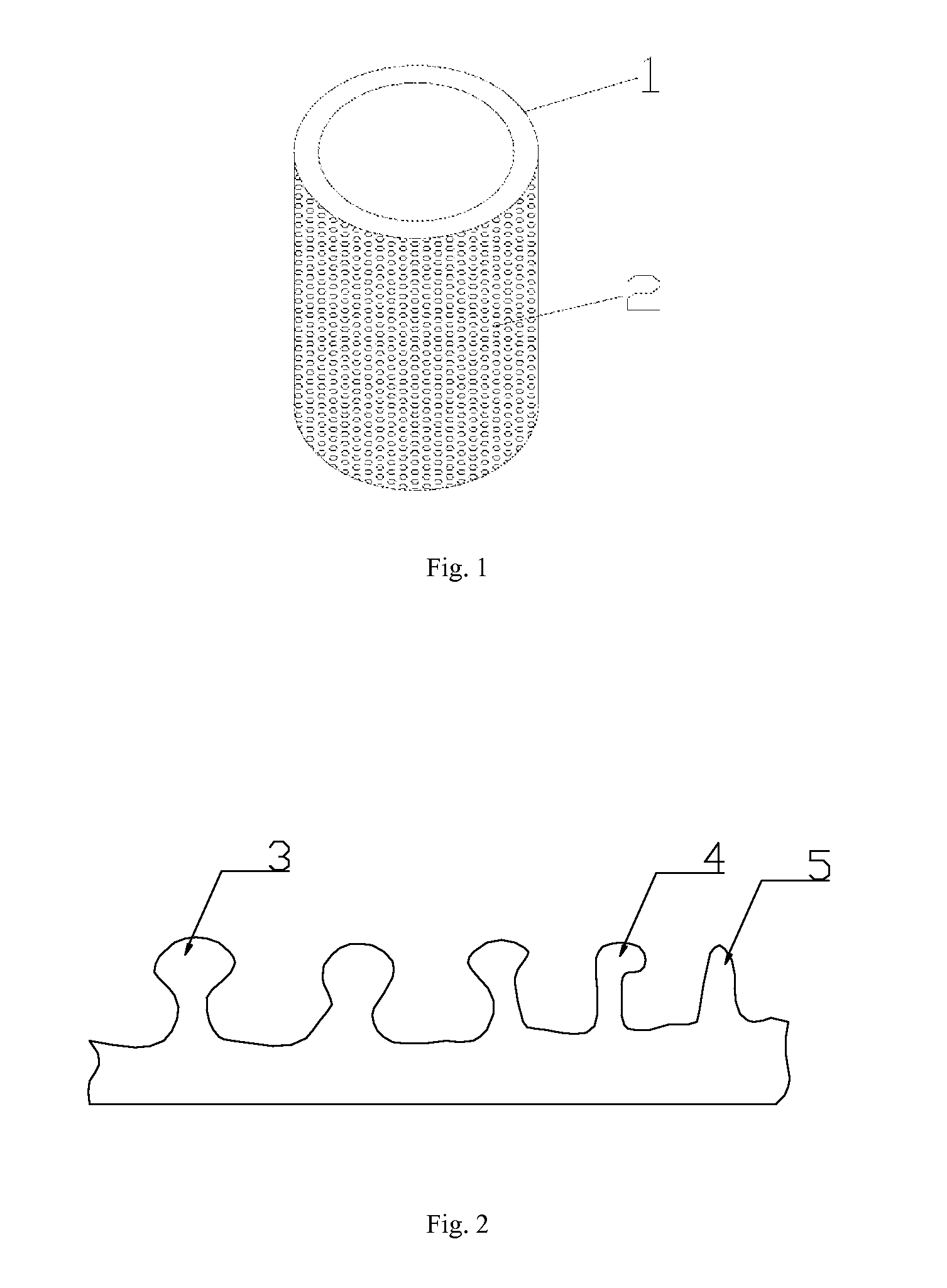
Cylinder liner and preparation method thereof
a technology of cylinder liner and cylinder body, which is applied in the direction of machines/engines, mechanical equipment, coatings, etc., can solve the problems of difficult to form ideal protrusions, difficult to fill molten materials used for manufacturing cylinder liner, and decrease the bite force between the cylinder liner material and the outside aluminum sheath, so as to improve the radial bearing capacity, improve the bite force, and improve the contact area
- Summary
- Abstract
- Description
- Claims
- Application Information
AI Technical Summary
Benefits of technology
Problems solved by technology
Method used
Image
Examples
embodiment 1
[0089]In the present embodiment, the method for manufacturing the cylinder liner comprises the following steps:
[0090](1) preparing ceramic paste with the following raw materials of respective weight percentages: 6% of adhesive (bentonite), 19% of diatomite, 0.08% of surfactant and 74.92% of soft water, wherein the ceramic paste is obtained by firstly mixing the adhesive, the diatomite and the soft water uniformly and then adding the surfactant;
[0091](2) with controlling the temperature at 230° C. and the rotating speed of 700±50 r / min, spraying a layer of the ceramic paste with a thickness of 1.0±0.1 mm onto the inner surface of a steel mould used for manufacturing the cylinder liner, wherein the ceramic paste is immediately subject to a microburst and then forms a ceramic protective layer having a Ω-shaped cavity;
[0092]It is necessary to carefully check whether there is exceptional condition such as defect, crack, or damage in the inner cavity of the mould before pouring. Meanwhile...
embodiment 2
[0110]In this embodiment, the method for manufacturing the cylinder liner includes the following steps:
[0111](1) preparing ceramic paste with the following raw materials of respective weight percentages: 4% of adhesive (bentonite), 23% of diatomite, 0.08% of surfactant and 72.92% of soft water, wherein the ceramic paste is obtained by firstly mixing the adhesive, the diatomite and the soft water uniformly and then adding the surfactant;
[0112](2) with controlling the temperature at 260° C. and the rotating speed of 700±50 r / min, spraying a layer of the ceramic paste with a thickness of 1.0±0.1 mm onto the inner surface of a steel mould used for manufacturing the cylinder liner, wherein the ceramic paste is immediately subject to a microburst and then forms a ceramic protective layer having a Ω-shaped cavity.
[0113]It is necessary to carefully check whether there is exceptional condition such as defect, crack, or damage in the inner cavity of the mould before pouring. Meanwhile it is n...
embodiment 3
[0129]In the present embodiment, the method for manufacturing the cylinder liner includes the following steps:
[0130](1) preparing ceramic paste with the following raw materials of respective weight percentages: 8% of adhesive (bentonite), 16% of diatomite, 0.08% of surfactant and 75.92% of soft water, wherein the ceramic paste is obtained by firstly mixing the adhesive, the diatomite and the soft water uniformly and then adding the surfactant;
[0131](2) with controlling the temperature at 240° C. and the rotating speed of 700±50 r / min, spraying a layer of the ceramic paste with a thickness of 1.0±0.1 mm onto the inner surface of a steel mould used for manufacturing the cylinder liner, wherein the ceramic paste is immediately subject to a microburst and then forms a ceramic protective layer having a Ω-shaped cavity.
[0132]It is necessary to carefully check whether there is exceptional condition such as defect, crack, or damage in the inner cavity of the mould before pouring. Meanwhile ...
PUM
| Property | Measurement | Unit |
|---|---|---|
| height | aaaaa | aaaaa |
| height | aaaaa | aaaaa |
| temperature | aaaaa | aaaaa |
Abstract
Description
Claims
Application Information
 - R&D
- Intellectual Property
- Life Sciences
- Materials
- Tech Scout
- Unparalleled Data Quality
- Higher Quality Content
- 60% Fewer Hallucinations
Browse by: Latest US Patents, China's latest patents, Technical Efficacy Thesaurus, Application Domain, Technology Topic, Popular Technical Reports.
© 2025 PatSnap. All rights reserved.Legal|Privacy policy|Modern Slavery Act Transparency Statement|Sitemap|About US| Contact US: help@patsnap.com


