
Rational approximate optimization method for unsteady aerodynamic load of aerodynamic servo elastic system

A technology of aerodynamic load and servo elasticity, which is applied in the direction of file system, file system type, design optimization/simulation, etc., can solve the problem of strong empirical constraints, unsatisfactory fitting effect of generalized unsteady aerodynamic coefficient matrix, and poor fitting effect. Ideal and other problems to achieve the effect of reducing the numerical fitting error

Active Publication Date: 2020-01-10
NORTHWESTERN POLYTECHNICAL UNIV +1
View PDF9 Cites 2 Cited by
  • Summary
  • Abstract
  • Description
  • Claims
  • Application Information

AI Technical Summary

Problems solved by technology

Document 1 "Application of aeroservoelastic modeling using minimum-state unsteadyaerodynamic approximations [J]. Journal of guidance, control, and dynamics, 1991, 14(6): 1267-1276" proposed a minimum-state rational approximate fitting algorithm, but The constraints of this algorithm are too empirical, and the fitting effect is not ideal; Document 2 "Method for aerodynamic unsteady forces time calculations on an F / A-18 aircraft[J]. Aeronautical Journal, 2008, 112(1127): 27-32" In the calculation of the unsteady aerodynamic load history of the specific aircraft, the Roger type least squares algorithm is used; Document 3 "ZAERO User's Manual.Version8.2, ZONA Technology Inc. March 2008" realizes the engineering algorithm program of the Roger type least squares algorithm engineering applications
However, these algorithms all fix the aerodynamic lag root, which makes the fitting effect of each element of the generalized unsteady aerodynamic coefficient matrix on multiple discrete frequency points unsatisfactory.

Method used

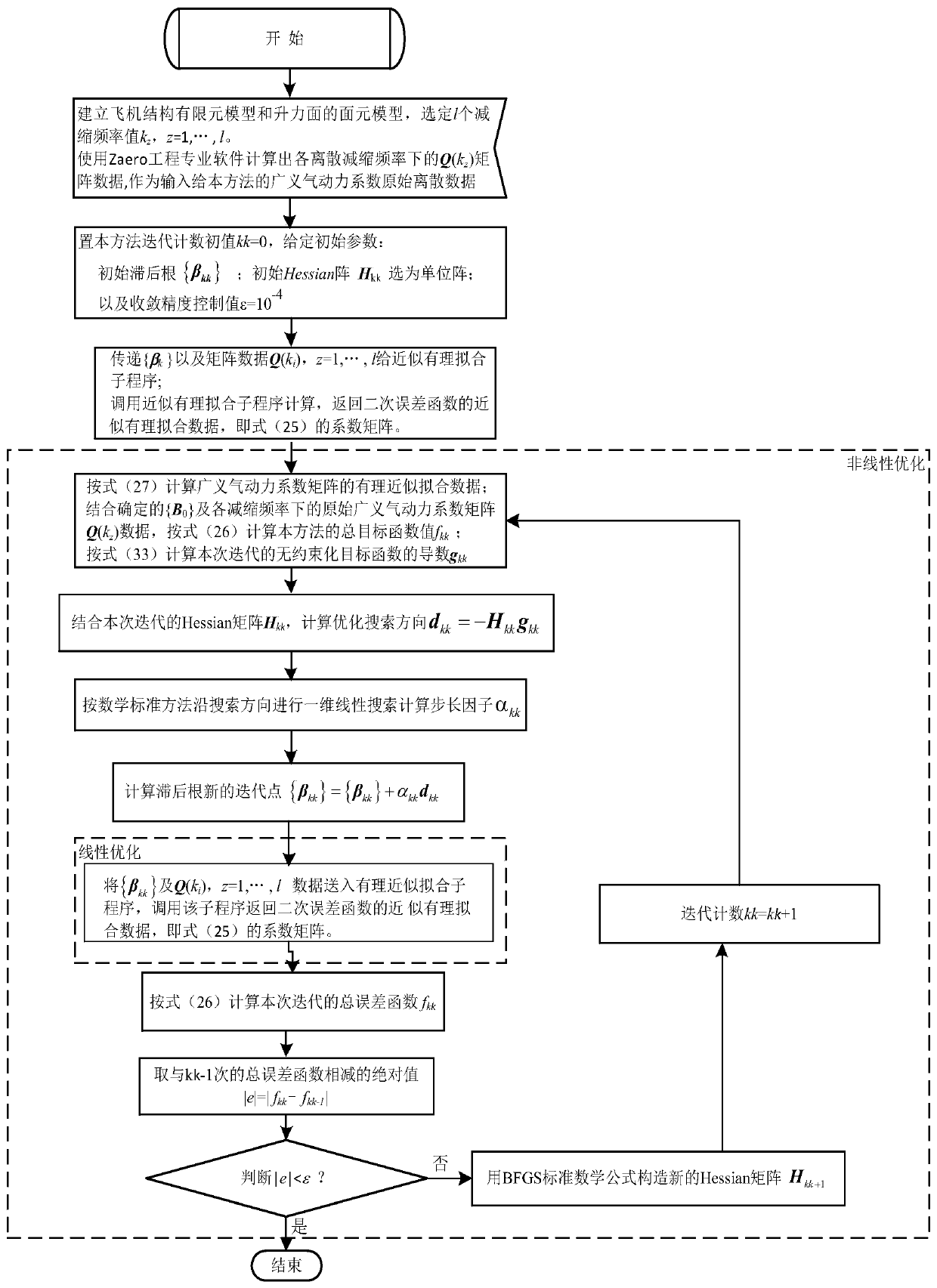

Image

  • Rational approximate optimization method for unsteady aerodynamic load of aerodynamic servo elastic system
  • Rational approximate optimization method for unsteady aerodynamic load of aerodynamic servo elastic system
  • Rational approximate optimization method for unsteady aerodynamic load of aerodynamic servo elastic system

Examples


Embodiment

[0157] like Figures 1 to 8 As shown, the present embodiment is a process of processing the generalized unsteady aerodynamic coefficient matrix of a thin-walled wing structure with a large aspect ratio, and the present invention is further described in conjunction with the accompanying drawings and embodiments.

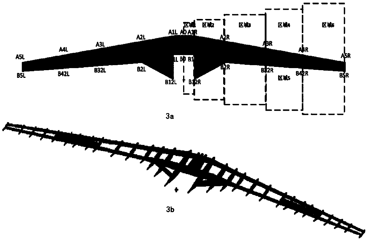
[0158] Step I, take out the CAD digital model data of the wing structure from the CATIA software. The geometric shape and internal skeleton structure of the UAV are as follows: figure 2 As shown, it can be divided into central wing, left and right outer wings, and the split points are A3L and A3R. The positions of key points are marked in the figure. The model is symmetrical about the midplane A0-B0. Table 1 shows the size parameters of the right half wing, and its half-span length is 8900mm.

[0159] Table 1 Wing plane dimension parameters

[0160] Location Length (mm) Location Length (mm) A0-B0 937.00 B31R-B32R 272.00 A1R-B12R 2141...


PUM


Abstract

The invention discloses a rational approximate optimization method for an unsteady aerodynamic load of an aerodynamic servo elastic system. Two types of original data of an analysis structure are obtained through existing commercial engineering numerical calculation software. On the basis, an unsteady aerodynamic force rational approximate expression form recognized by modern engineering analysisis applied, and a two-stage alternating double-iteration numerical optimization algorithm of two variables including a linear term coefficient and a nonlinear term coefficient is established. Two-stage double optimization iteration is performed until an optimal coefficient in a high-precision rational approximate fitting formula is obtained. The prediction precision of the unsteady aerodynamic load process in modeling analysis of the aerodynamic servo elastic system of the airplane selected structure is improved, rational approximate fitting errors are greatly reduced, and therefore high-precision load process numerical values are provided for dynamic response, dynamic stability and active elastic control of the airplane aerodynamic servo elastic system.

Description

technical field [0001] The invention relates to the field of aeroelasticity, in particular to a rational approximation optimization method for unsteady aerodynamic loads of an aeroservoelastic system. Background technique [0002] The aircraft deflects the control surface according to the control command, so that the aircraft changes the original flight trajectory, that is, various maneuvering actions of the aircraft are formed. The aerodynamic load history, also known as unsteady aerodynamic force, is formed on the lift surface of the aircraft during maneuvering flight. This changing load history will inevitably lead to elastic vibration of the structure; otherwise, the elastic vibration will affect the unsteady aerodynamic force. The most unfavorable situation of the coupling is that the amplitude of the lifting surface is self-excited and amplified. In the light case, the aircraft is difficult to control, and in the severe case, the structure is damaged. Therefore, in en...

Claims


Application Information

Patent Timeline
IPC IPC(8): G06F30/23G06F30/15G06F16/18
CPCY02T90/00
Inventor 孙秦艾俊强刘彦杰蒲立东
Owner NORTHWESTERN POLYTECHNICAL UNIV
Learn More