
Conductive cone, cable terminal and cable intermediate joint

A technology of cable intermediate joints and conductive cones, which is applied in the direction of cable accessories, cable installation, electrical components, etc., can solve the problems of low sensitivity, long optical propagation path of conductive cones, limited application range, etc., and achieve high sensitivity and wide application range Wide, the effect of improving sensitivity

Inactive Publication Date: 2020-01-10
GLOBAL ENERGY INTERCONNECTION RES INST EURO GMBH +3
View PDF9 Cites 5 Cited by
  • Summary
  • Abstract
  • Description
  • Claims
  • Application Information

AI Technical Summary

Problems solved by technology

[0003] Therefore, the technical problem to be solved by the present invention is to overcome the shortcomings of the conductive cone in the prior art that the optical propagation path is long, the scope of application is limited, and the sensitivity is low, thereby providing a short optical propagation path, wide application range, local Conductive cones, cable terminations and cable intermediate joints with high discharge monitoring sensitivity

Method used


Image

  • Conductive cone, cable terminal and cable intermediate joint
  • Conductive cone, cable terminal and cable intermediate joint
  • Conductive cone, cable terminal and cable intermediate joint

Examples


Embodiment Construction

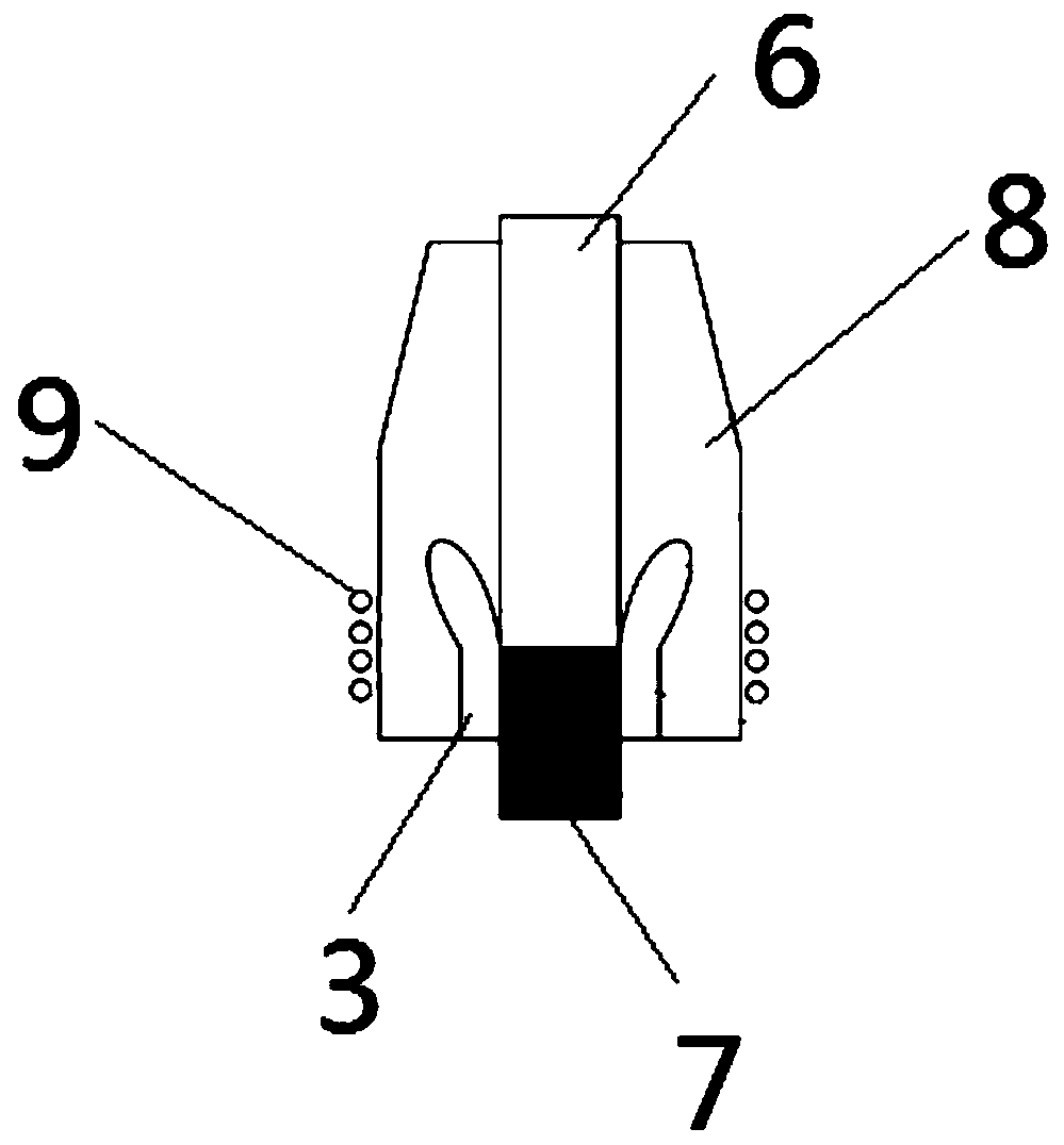
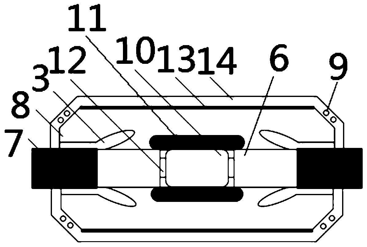
[0025] The technical solutions of the present invention will be clearly and completely described below in conjunction with the accompanying drawings. Obviously, the described embodiments are part of the embodiments of the present invention, rather than all of them. Based on the embodiments of the present invention, all other embodiments obtained by those of ordinary skill in the art without creative work shall fall within the protection scope of the present invention.

[0026] In addition, the technical features involved in the different embodiments of the present invention described below can be combined with each other as long as there is no conflict between them.

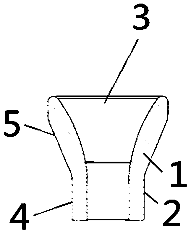
[0027] Such as figure 1 A specific implementation of the conductive cone shown includes a first transparent insulator 1 arranged inside and a transparent conductive layer 2 covering the outside. The transparent conductive layer 2 completely covers the first transparent insulator 1. The first transparent insulator 1 is...


PUM


Abstract

The invention relates to the technical field of power cable accessories, in particular to a conductive cone, a cable terminal and a cable intermediate joint. The conductive cone comprises a first transparent insulator arranged inside and a transparent conductive layer covering the outside, and the transparent conductive layer completely covers the first transparent insulator. The cable terminal comprises the conductive cone, and the conductive cone is arranged at the joint of the insulating layer of the cable and the semi-conductive insulating shielding layer of the cable in a sleeving manner.The cable intermediate joint comprises a pair of conductive cones, the pair of conductive cones are oppositely arranged, the conductive cones are arranged at the joint of the insulating layer of thecable and the semi-conductive insulating shielding layer of the cable in a sleeving mode, and a pair of cable conductors located in the center of the cable joint are fixed through a connecting structure. The invention provides the conductive cone, the cable terminal and the cable intermediate joint which are wide in application range and high in partial discharge monitoring sensitivity.

Description

Technical field [0001] The invention relates to the technical field of power cable accessories, in particular to a conductive cone, a cable terminal and a cable intermediate joint. Background technique [0002] The interface between the stress cone of the cable accessory and the cable insulation is the weakest link in the cable accessory. When the interface has defects or the interface pressure is insufficient, partial discharge may occur here under the action of the electric field. In order to perform optical measurement of the partial discharge phenomenon, at least one optical path that allows the partial discharge optical signal to penetrate the stress cone and propagate outward needs to be provided inside the cable accessory. At present, there is a method of using transparent insulating silicon rubber material to achieve partial discharge measurement inside the stress cone, but its conductive cone is made of black opaque material, so the partial light discharge line can only ...

Claims


Application Information

Patent Timeline
Patent Type & Authority Applications(China)
IPC IPC(8): H02G15/064G01R31/12
CPCG01R31/1218H02G15/064
Inventor 罗艺王海田韩正一周明瑜尹立周育桢张翀翟雪冰
Owner GLOBAL ENERGY INTERCONNECTION RES INST EURO GMBH
Learn More