Magnetic confinement rocker arm type vibration power generation device and system

A technology of vibration power generation and power generation system, applied in the direction of electromechanical devices, magnetic circuit shape/style/structure, reciprocating/swinging/vibrating magnetic circuit components, etc., can solve the problem of narrow response frequency band, low vibration energy conversion efficiency, and energy conversion efficiency To achieve the effect of widening the response frequency band, high energy conversion efficiency and high flexibility

Inactive Publication Date: 2020-01-10
SOUTHWEST UNIVERSITY
View PDF7 Cites 2 Cited by
  • Summary
  • Abstract
  • Description
  • Claims
  • Application Information

AI Technical Summary

Problems solved by technology

[0004] However, the traditional shaking power generation scheme has the following disadvantages. The existing linear system has a narrow response frequency band. At present, most of the existing shaking power generation devices belong to the linear system. Generally speaking, the linear system can only achieve the maximum energy near the resonance frequency of the system. capture, while around other frequency points, the energy conversion efficiency drops sharply
However, the existing common sloshing phenomena generally have a wide frequency band, so systems with a narrow response frequency band generally have low conversion efficiency of sloshing energy.

Method used


Image

  • Magnetic confinement rocker arm type vibration power generation device and system
  • Magnetic confinement rocker arm type vibration power generation device and system
  • Magnetic confinement rocker arm type vibration power generation device and system

Examples


Embodiment 1

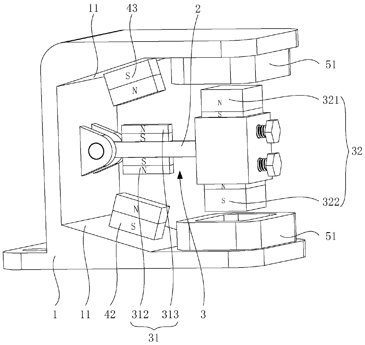
[0052] In this embodiment one, if figure 1 As shown, the vibration confinement magnet assembly 31 includes a first vibration confinement magnet 312 and a second vibration confinement magnet 313, and a plurality of fixed confinement magnets 41 includes a first fixed confinement magnet 42 and a second fixed confinement magnet 43; the first fixed confinement magnet 42 Mutual repulsion with the first vibration confinement magnet 312 so that the rocking arm 2 moves toward the second fixed confinement magnet 43; sports.

[0053] by figure 1 As an example for specific description, such as figure 1 As shown, the rocker arm 2 swings around a certain axis. When the rocker arm 2 swings downward, the first vibration confinement magnet 312 is close to the first fixed confinement magnet 42. The distance between the first vibration confinement magnet 312 and the first fixed confinement magnet 42 The intermagnetic repulsion gradually increases, so that the rocking arm 2 moves toward the se...

Embodiment 2

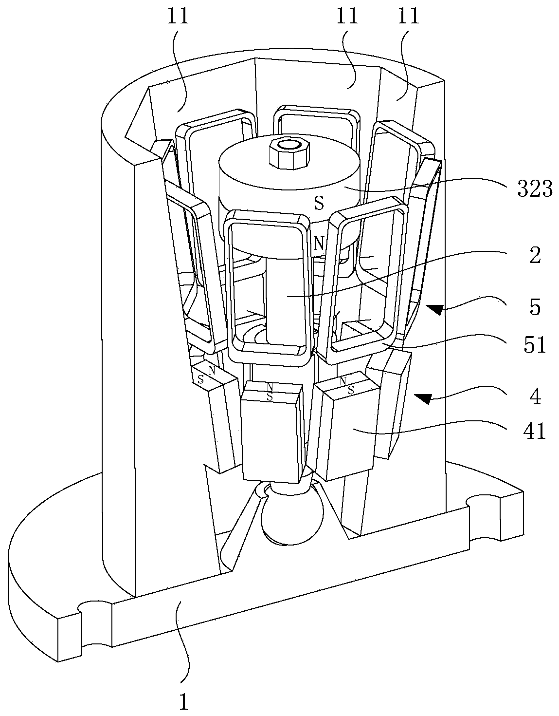
[0060] In the second embodiment, the fixed and constrained magnet assembly 4 includes two, three or even more fixed and constrained magnets 41. When the fixed and constrained magnet assembly 4 includes two fixed and constrained magnets 41, the two fixed and constrained magnets 41 are bent to form arc to surround the rocker arm 2; when the fixed constrained magnet assembly 4 includes more than three fixed constrained magnets 41, a plurality of fixed constrained magnets 41 are distributed around the axis of the rocker arm 2.

[0061] Specifically, the fixed and constrained magnet assembly 4 may include two, three, four, five, six, seven, eight and other fixed and constrained magnets 41 .

[0062] by figure 2 As an example for specific description, the fixed and constrained magnet assembly 4 includes eight fixed and constrained magnets 41 , each fixed and constrained magnet 41 is arranged on the fixed frame 1 , and the eight fixed and constrained magnets 41 are evenly distribute...


PUM


Abstract

The invention provides a magnetic confinement rocker arm type vibration power generation device and system, and relates to the technical field of power generation systems. The magnetic confinement rocker arm type vibration power generation device provided by the invention comprises a fixed frame and a rocker arm hinged to the fixed frame, wherein the rocker arm is provided with a magnetic body, the fixed frame is provided with a fixed confinement magnet assembly and a coil assembly, the fixed confinement magnet assembly and the magnetic body are in mutual exclusion to provide a restoring forcefor the rocker arm, and the coil assembly and the magnetic body are matched to generate electricity. According to the magnetic confinement rocker arm type vibration power generation device provided by the invention, the response frequency band can be broadened, broadband shaking energy collection is achieved, the energy conversion efficiency is high, the driving of water or other media is not needed, and high flexibility is achieved.

Description

technical field [0001] The invention relates to the technical field of power generation systems, in particular to a magnetically constrained rocker arm type vibration power generation device and system. Background technique [0002] With the advancement of society and the development of science and technology, the demand for energy in human society is increasing, and traditional fossil energy is difficult to meet human demand for energy. Therefore, the development of new energy has become a current research hotspot. The surrounding environment contains a large amount of clean energy such as solar energy, wind energy, water energy, vibration or shaking mechanical energy, which provides conditions for the development of new energy. [0003] According to the principle of energy conversion, the existing shaking power generation schemes can be roughly divided into three types: electromagnetic, piezoelectric, and electrochemical. The electromagnetic shaking power generation devic...

Claims


Application Information

Patent Timeline
Patent Type & Authority Applications(China)
IPC IPC(8): H02K35/02H02K1/34
CPCH02K1/34H02K35/02
Inventor 高鸣源李云伍石军锋
Owner SOUTHWEST UNIVERSITY
Why Eureka
Try Eureka