Novel slotted disc type permanent magnet eddy current coupling

A permanent magnet eddy current, grooved disc technology, applied in the direction of permanent magnet clutch/brake, electric brake/clutch, electrical components, etc., can solve the problems of reducing the utilization efficiency of magnetic materials, increasing the heat dissipation burden of equipment, and increasing eddy current loss, etc. Achieve the effect of torque fluctuation reduction, reasonable spatial distribution, and reduction of torque fluctuation

Pending Publication Date: 2020-01-10
TAIER HEAVY IND +1
View PDF0 Cites 8 Cited by
  • Summary
  • Abstract
  • Description
  • Claims
  • Application Information

AI Technical Summary

Problems solved by technology

The disadvantage of the first structural scheme is that the proportion of ineffective eddy currents in the conductor area that do not contribute to the generation of torsion is relatively large, thereby increasing redundant eddy current losses. Since eddy current losses are the main power loss of permanent magnet eddy current transmissions, it reduces The utilization efficiency of magnetic materials; at the same time, the excess eddy current loss is finally converted into heat energy, which increases the heat dissipation burden of the equipment
The disadvantage of the second structural scheme is that the copper conductor disk of the disc permanent magnet eddy current coupling is slotted, and the slotted space is filled with magnetically permeable material, which can improve the transmission torque of the device, but at the same time will greatly increase Torque ripple, limiting its application in some occasions requiring precise torque control

Method used


Image

  • Novel slotted disc type permanent magnet eddy current coupling
  • Novel slotted disc type permanent magnet eddy current coupling
  • Novel slotted disc type permanent magnet eddy current coupling

Examples


Embodiment 1

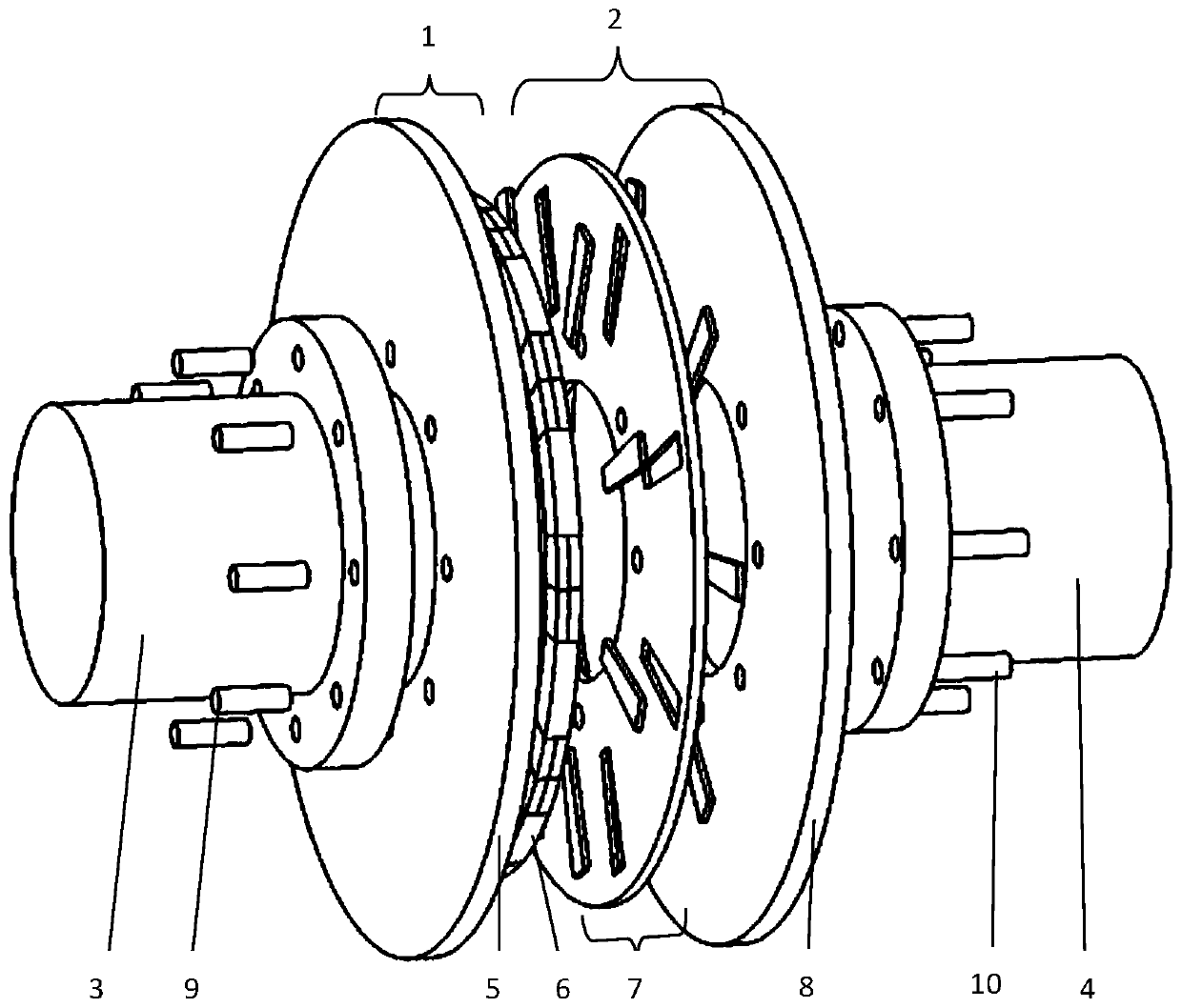
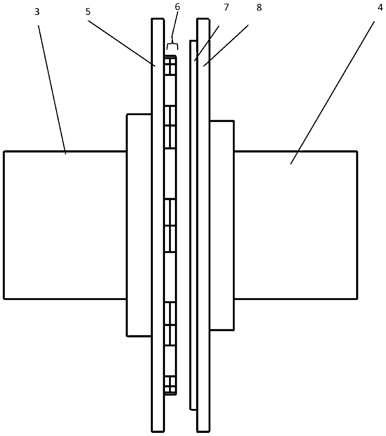
[0026] From figure 1 , figure 2 , Figure 4 , Figure 5 , Figure 6 It can be seen that the slotted disc permanent magnet eddy current coupling of the present invention includes a driving disc 1, a driving shaft 3, a driven disc 2, and a driven shaft 4, and the driving disc 1 and the driving shaft 3 are coaxially arranged and connected to each other. , the driven disk 2 and the driven shaft 4 are coaxially arranged and connected, the driving disk 1 and the driven disk 2 are coaxially arranged, the driving disk 1 includes the back iron disk I5, the magnetic coil 6, the back iron disk I5 and the magnet The ring 6 is coaxially arranged, and the magnetic ring 6 is fixed on the inner surface of the back iron plate I5 opposite to the driven plate 2, and the back iron plate I5 and the driving shaft 3 are connected through the connecting column I9; the driven plate 2 includes an eddy current combination plate 7. The back iron plate Ⅱ8, the eddy current combination plate 7 and the...

Embodiment 2

[0031] From Figure 4 , Figure 5 , Figure 6It can be seen that, as a preferred mode of the present invention, the shapes and sizes of all grooves on the left end face of the vortex disk body 15 are the same, the depth of the grooves is less than the thickness of the eddy current disk body 15, and the shape and size of the left iron block 16 are the same as those of the vortex disk. The grooves on the left end surface of the body 15 have the same shape and size. The shape and size of all the grooves on the right end face of the swirl disc body 15 are the same, the depth of the groove is less than the thickness of the swirl disc body 15, the shape and size of the right iron block 17 are the same as the shape and size of the grooves on the right end face of the swirl disc body 15 same.

[0032] The left iron block 16 , the right iron block 17 and the swirl disc body 15 are fixed by bonding or clamping. As long as the stability of the connection between the left iron block 1...

Embodiment 3

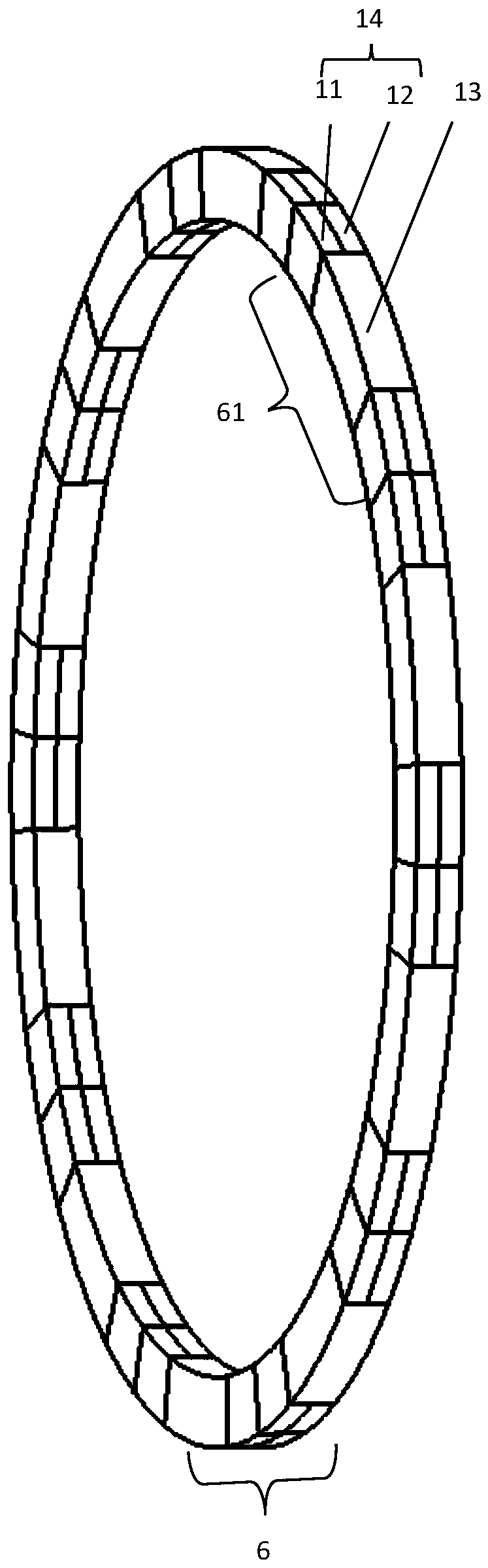
[0036] From image 3 , Figure 7 It can be seen that in the slotted disc permanent magnet eddy current coupling of the present invention: the magnetic coil 6 is formed into a ring by a plurality of mixed magnetic poles 61, and each mixed magnetic pole 61 is a fan ring structure with the same shape and size. The direction of the resultant magnetic field is along the axial direction of the drive disk 1 , and the direction of the resultant magnetic field of adjacent mixed magnetic poles 61 is opposite.

[0037] Wherein, each hybrid magnetic stage 61 comprises a magnetic block 13, a magnetic gathering unit 14 symmetrically arranged on the left and right sides of the magnetic block 13; The block 13 has the same thickness along the axial direction of the driving disk 1 , and the magnetization unit 14 and the magnetic block 13 have the same size along the radial direction of the driving disk 1 .

[0038] From Figure 7 It can be seen that the mixed magnetic poles in the magnetic c...


PUM


Abstract

The invention discloses a novel slotted disc type permanent magnet eddy current coupling comprising a driving disc, a driving shaft, a driven disc and a driven shaft. The driving disc includes a backiron disc I and a magnetic ring. The driven disc includes an eddy current combined disc and a back iron disc II. The eddy current combined disc consists of an eddy current disc body, a plurality of left iron blocks and a plurality of right iron blocks; rectangular grooves or fan-shaped grooves distributed in an annular array are distributed in the left end face and the right end face of the eddy current disc body, wherein the numbers of the grooves in the left end face and the right end face are equal; the grooves formed in the left end face and the right end face are staggered in a circumferential direction of the eddy current disc body; and the position of any groove in the left end face is not overlapped with the position of any position of any groove in the right end face in the circumferential direction of the eddy current disc body. One left iron block is arranged in each groove in the left end face of the eddy current disc body; and one right iron block is arranged in each groove in the right end face of the eddy current disc body. With the novel slotted disc type permanent magnet eddy current coupling, the torque fluctuation is greatly reduced while the transmission torqueof the coupling is effectively improved.

Description

technical field [0001] The invention relates to the technical field of permanent magnet eddy current transmission, in particular to a disc type permanent magnet eddy current coupling. Background technique [0002] The basic principle of the permanent magnet eddy current coupling is: when the permanent magnet rotor and the conductor rotor rotate relative to each other, the permanent magnets arranged alternately in the magnetic pole direction on the permanent magnet rotor will be in the eddy current ring made of conductive material in the conductor rotor. An alternating magnetic field is generated, and then an alternating eddy current is induced in it, and the eddy current generates an induced magnetic field in the eddy current ring, and the induced magnetic field interacts with the magnetic field on the permanent magnet rotor, so that there A coupling moment is generated between them, so as to achieve the function of transmitting motion and torque. [0003] The structural fo...

Claims


Application Information

Patent Timeline
Patent Type & Authority Applications(China)
IPC IPC(8): H02K49/10
CPCH02K49/108
Inventor 殷磊朱长江郑明睿石珍强马计委孙宇陈科郑红梅肖士喜
Owner TAIER HEAVY IND
Why Eureka
Try Eureka