Cubic buck converter

A technology of converters and power inductors, which is applied in the field of three-time step-down converters, can solve the problems that cannot meet the needs of practical applications, and the voltage gain range of step-down converters is small, and achieve simple structure, convenient control, and expanded gain range Effect

Pending Publication Date: 2020-01-10
SHANGHAI SHENCHUAN ELECTRIC CO LTD
View PDF0 Cites 2 Cited by
  • Summary
  • Abstract
  • Description
  • Claims
  • Application Information

AI Technical Summary

Problems solved by technology

[0002] The voltage gain of traditional buck converters has a small variation range, and usually the output voltage can only be 0.1-0.9 times the input voltage, which cannot meet the needs of practical applications in many cases.

Method used


Image

  • Cubic buck converter
  • Cubic buck converter
  • Cubic buck converter

Examples


Embodiment

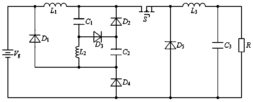
[0022] Embodiment: The third-order step-down converter in this embodiment utilizes the inherent characteristics of the inductor-capacitor-diode network to realize the expansion of the voltage gain of the step-down converter.

[0023] Such as figure 1 As shown, the tertiary buck converter in this embodiment includes the input power supply V g , the power switch tube S, the first power inductor L 1 , the second power inductor L 2 , the third power inductor L 3 , the first intermediate storage capacitor C 1 , the second intermediate storage capacitor C 2 , the output capacitance C 3 , the first diode D 1 , the second diode D 2 , the third diode D 3 , the fourth diode D 4 , the fifth diode D 5 , load R.

[0024] where the input supply V g The anodes of the first diode D are respectively connected to the 1 The cathode, the first power inductor L 1 one end of the connection;

[0025] The first power inductor L 1 The other end of the first intermediate energy storage ...


PUM


Abstract

The invention relates to the technical field of power electronic converters and electric energy conversion, particularly to a cubic buck converter. On the basis of intrinsic characteristics of an inductor-capacitor-diode network, three power inductors store energy at the same time and two intermediate energy storage capacitors release energy externally when a power switch tube is turned on; and when the power switch tube is turned off, the three power inductors release the stored energy to two intermediate energy storage capacitors and a load. Therefore, the high buck of the output voltage isrealized by using one power switch tube and thus the value of the output voltage is D3 times that of the input voltage, wherein the D expresses a duty ratio of the power switch tube when the converterworks.

Description

technical field [0001] The invention relates to the technical field of power electronic converters and electric energy conversion, in particular to a three-time step-down converter. Background technique [0002] The range of voltage gain of the traditional buck converter is small, and the output voltage is usually only 0.1-0.9 times the input voltage, which cannot meet the needs of practical applications in many cases. Contents of the invention [0003] The purpose of the present invention is to provide a three-time step-down converter according to the above-mentioned deficiencies in the prior art, which utilizes the inherent characteristics of the inductor-capacitor-diode network to realize the step-down converter by switching the on-off state of the power switch tube Expansion of gains. [0004] The object of the present invention is realized by the following technical solutions: [0005] A three-time step-down converter, characterized in that it includes an input powe...

Claims


Application Information

Patent Timeline
Patent Type & Authority Applications(China)
IPC IPC(8): H02M3/156
CPCH02M3/156
Inventor 郑昌陆张能郑益飞
Owner SHANGHAI SHENCHUAN ELECTRIC CO LTD
Why Eureka
Try Eureka