Feedback amplifier and audio system thererof

a technology of feedback amplifier and audio system, which is applied in the field of electronic circuit techniques, can solve the problems of reducing noise performance, signal-to-noise ratio (snr), and parasitic resistance at rb, and achieves the effects of reducing noise, wide gain range, and consuming less chip area

Active Publication Date: 2010-05-27
NUVOTON
View PDF1 Cites 1 Cited by
  • Summary
  • Abstract
  • Description
  • Claims
  • Application Information

AI Technical Summary

Benefits of technology

[0027]Many benefits are achieved by way of the present invention over conventional techniques. For example, an embodiment of the present invention provides an easy to use design that is compatible with conventional integrated circuit design and fabrication process technologies. In embodiments of the present invention, techniques are provided for an amplifier having an adjustable gain over a wide gain range. In a specific embodiment, an amplifier is provided that has only one operational amplifier and a voltage divider having two resistors. Such design can consumes less chip area and consumes less current than conventional amplifiers having two operational amplifiers. In some embodiments, less flicker noise is generated because only one amplifier is needed as compared to conventional two-amplifier designs. Additionally, better gain accuracy can be achieved in part because the operation amplifier circuit does not need a small resistance component in a critical path.

Problems solved by technology

The low resistance of r2 results in a parasitic resistance at r2 due to layout mismatch and long metal routing and the operation of the single-stage feedback amplifier 100 suffers a gain offset.
In addition, two operational amplifiers can contribute more noise sources and degrade the noise performance and signal-to-noise ration (SNR).

Method used


Image

  • Feedback amplifier and audio system thererof
  • Feedback amplifier and audio system thererof
  • Feedback amplifier and audio system thererof

Examples


Embodiment Construction

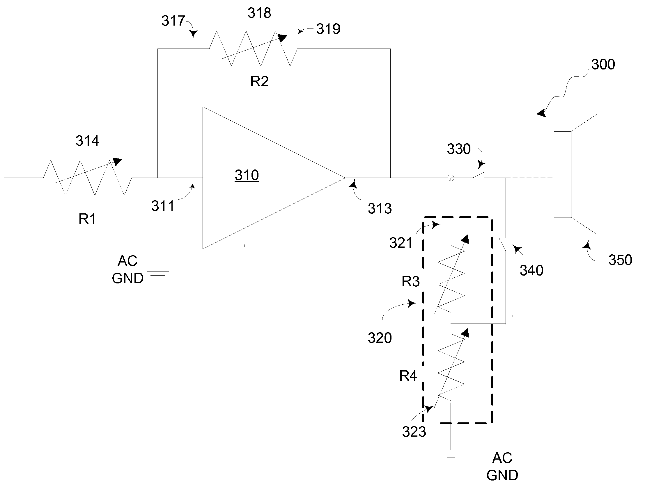
[0033]Embodiments of the present invention relate to audio systems and feedback amplifiers providing a wide range gain from about 6 dB to about −57 dB. The wide range gain can be achieved by operably coupling a voltage divider to an operational amplifier. In a specific embodiment the operational amplifier is coupled to resistors having resistance R1 and R2, which provides a gain of about 20*log(R2 / R1) in dB. The voltage divider is coupled with an output end of the operational amplifier if the feedback amplifier provides attenuation. In embodiments, the voltage divider can provide resistances R3 and R4 which provide attenuation of about −20*log(R4 / (R3+R4)). The exemplary feedback amplifier can provide a gain of about 20*log(R2 / R1)+20*log(R4 / (R3+R4)) in dB. By using the voltage divider, the feedback amplifier can provide the wide range gain, having a small chip size and low current consumption.

[0034]FIG. 3 is a schematic drawing illustrating an exemplary feedback amplifier coupled wit...


PUM


Abstract

A feedback amplifier includes an operational amplifier having an input end and an output end. A first resistor is coupled with the input end of the operational amplifier. A second resistor has a first end coupled with the input end of the operational amplifier and a second end coupled with the output end of the amplifier. A voltage divider has a first end being operably coupled with the output end of the operational amplifier and a second end being analog grounded. In an embodiment, the feedback amplifier further includes a first switch coupled to the first end of the voltage divider and the output end of the operational amplifier, and a second switch coupled to an internal node of the voltage divider. In an embodiment, the feedback amplifier is configured to provide attenuation when the first switch is open and second switch is closed.

Description

FIELD OF THE INVENTION[0001]The present invention relates to electronic circuit techniques. More particularly, the present invention relates to feedback amplifiers and audio systems thereof.BACKGROUND OF THE INVENTION[0002]Amplifier circuits have been used in various electronic devices such as audio devices. Amplifier circuits increase powers and / or amplitudes of signals. In many applications, power amplifier circuits are used at the output stage of a system to drive an external device. For example, an output power amplifier has been used to drive an external speaker. The output power amplifier may need to provide a gain from about −57 dB to about 6 dB for the audio system.[0003]FIG. 1 is a conventional single-stage feedback amplifier. In FIG. 1, the single-stage feedback amplifier 100 includes an operational amplifier 110 and resistors having resistances r1 and r2. The single-stage feedback amplifier 100 provides a gain of about 20*log(r2 / r1). In order to obtain a gain of about −57...

Claims


Application Information

Patent Timeline
Patent Type & Authority Applications(United States)
IPC IPC(8): H03G3/20H03F1/00
CPCH03F3/187H03F3/45475H03F2200/03H03F2200/411H03F2203/45522H03G7/002H03F2203/45611H03F2203/45688H03F2203/45721H03G1/0035H03F2203/45591
Inventor MUI, VINCENTWONG, LANCERAINA, ADITYA
Owner NUVOTON
Why Eureka
Try Eureka