Gas monitoring method and system and computer storage medium

A monitoring system and gas technology, applied in the field of network communication, can solve the problems of monitoring interruption, low transmission efficiency, and great influence of real-time monitoring, etc., and achieve the effects of improving stability, saving costs, and rapid and stable information transmission rate

Inactive Publication Date: 2020-01-10
深圳市中燃科技有限公司
View PDF5 Cites 0 Cited by
  • Summary
  • Abstract
  • Description
  • Claims
  • Application Information

AI Technical Summary

Problems solved by technology

[0007] Although this gas pipeline network monitoring method can monitor the pipeline network system in real time, due to the poor transmission stability and low transmission efficiency of GPRS itself, in daily use, it is prone to monitoring interruption and large delay, which affects real-time monitoring. bigger

Method used


Image

  • Gas monitoring method and system and computer storage medium
  • Gas monitoring method and system and computer storage medium

Examples


Embodiment 1

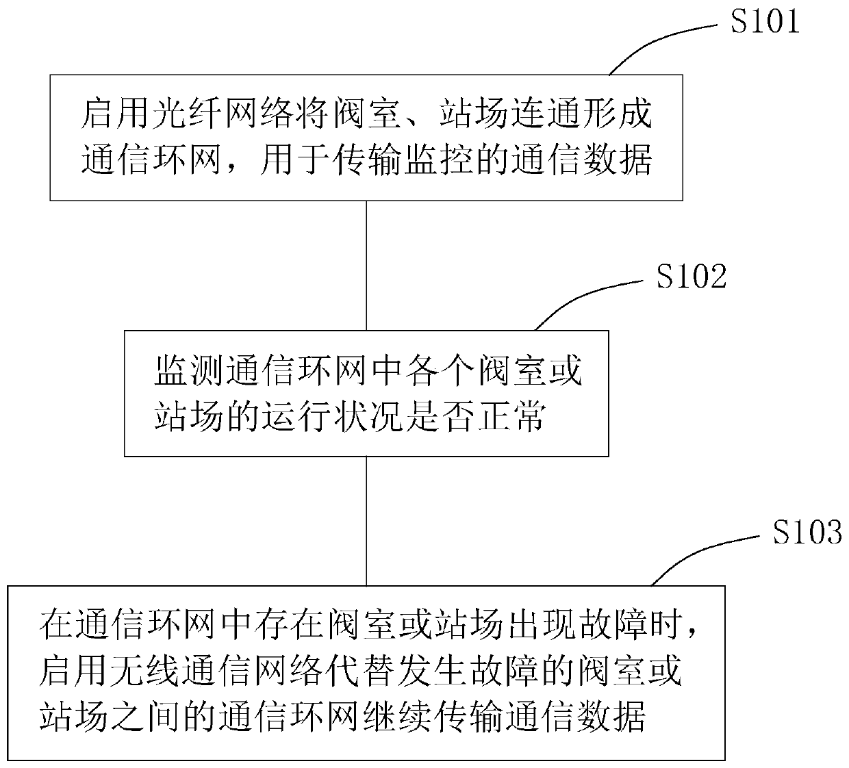
[0052] A gas monitoring method, with reference to figure 1 , including step S101 to step S105.

[0053] Step S101: Enable the optical fiber network to connect the valve room and the station to form a communication ring network for transmitting monitoring communication data.

[0054] The valve room and station field included in the gas transmission line of the optical fiber network are connected to form a closed and redundant communication ring network, which can transmit the communication data of the monitoring point more stably.

[0055] Step S102: Monitor whether the operating conditions of each valve room or station in the communication ring network are normal.

[0056] The communication data is transmitted through the communication ring network. On the one hand, the gas transmission is monitored, and on the other hand, the operating conditions of the valve chamber and the station are monitored.

[0057] Step S103: When there is a valve chamber in the communication ring n...

Embodiment 2

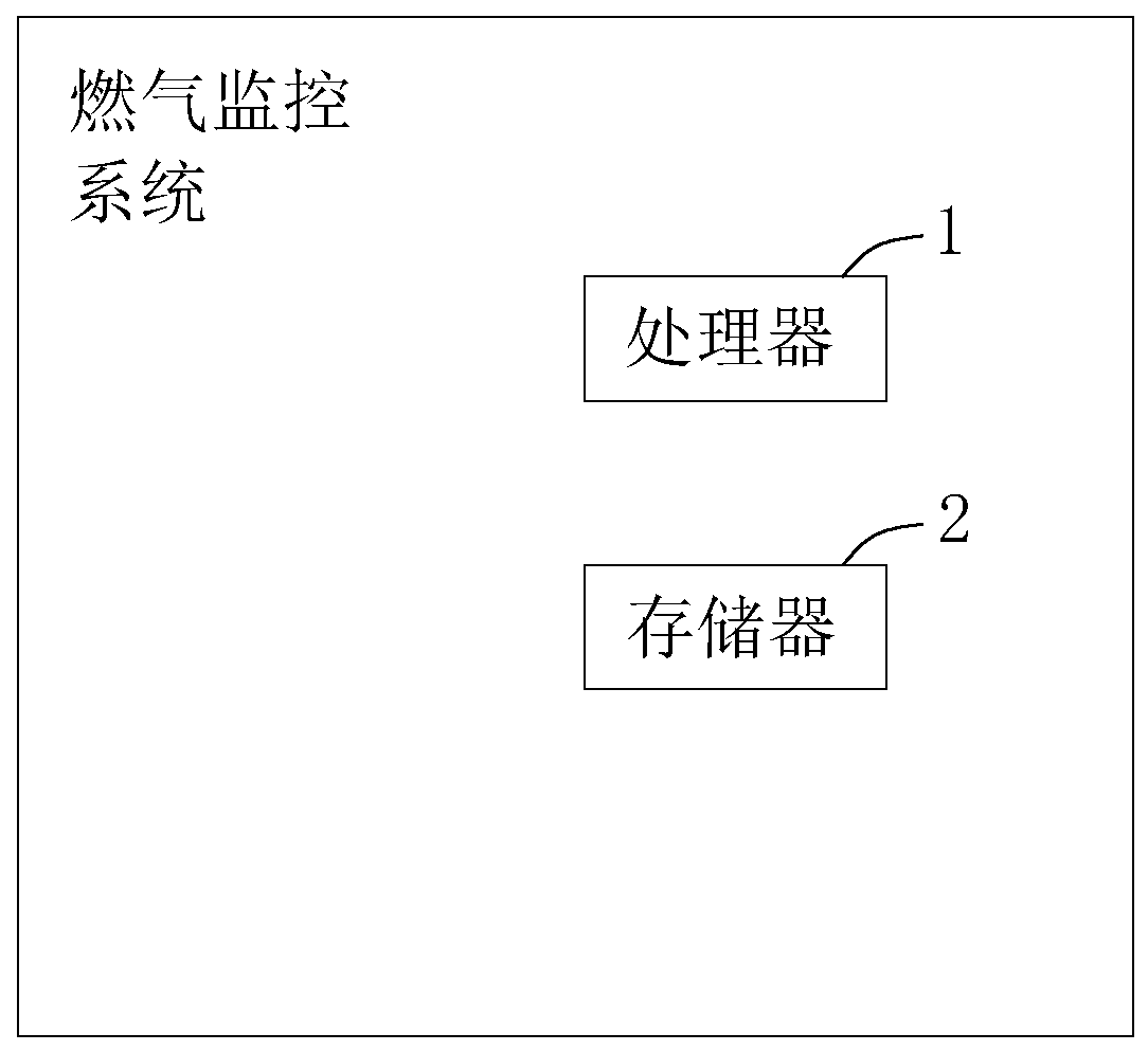
[0062] A gas monitoring system, with reference to figure 2 , including a processor 1 and a memory 2, the memory 2 stores an instruction set for the processor 1 to call to achieve:

[0063] The valve room and the station are connected through the optical fiber network to form a communication ring network to transmit communication data, and

[0064] When there are valve chambers or station failures in the communication ring network, the wireless communication network is used to replace the communication ring network between the faulty valve chambers or stations to continue to transmit communication data.

[0065] Enable the wireless communication network to replace the communication ring network between the faulty valve room or station to continue to transmit communication data, including,

[0066] Determine the adjacent communicating valve room or station based on the faulty valve room or station;

[0067] Enable wireless communication network between adjacent communicating ...

Embodiment 3

[0073] A computer storage medium stores a computer program for calling by a computer to realize the functions of the gas monitoring method in Embodiment 2.


PUM


Abstract

The invention discloses a gas monitoring method and system and a computer storage medium. The invention relates to network communication, and provides the following technical scheme that a valve chamber and a station yard are communicated through an optical fiber network to form a communication ring network for transmitting communication data, and when the valve chamber or the station yard breaksdown in the communication ring network, a wireless communication network is started to replace the communication ring network between the broken-down valve chamber or the broken-down station yard to continue transmitting the communication data. The valve chamber and the station yard are communicated through the optical fiber network to form a communication ring network, the information transmission rate of the communication mode of the optical fibers is rapid and stable, and meanwhile the networking cost can be saved through the communication ring network. When a communication fault occurs ina valve chamber or a station yard, a wireless communication network is started to replace a faulted communication ring network to continue to transmit communication data, the two communication modes are in seamless butt joint, continuity of monitoring is guaranteed, and stability of monitoring is improved.

Description

technical field [0001] The present invention relates to network communication, more specifically, it relates to a gas monitoring method, system and computer storage medium. Background technique [0002] In the early days, the monitoring technology of most gas supply units in my country was relatively backward, especially for the management of the transmission and distribution pipeline network. The error is high, and it is difficult to realize real-time data collection of monitoring points. Adopting the traditional transmission and distribution network management method, first of all, the operation cost is high, especially it is difficult to adapt to the requirements of modern management methods, which has caused huge economic losses and waste of resources to the country and enterprises. [0003] The data communication used in the existing pipe network monitoring system can be simply divided into two categories: wired communication and wireless communication, in which wired c...

Claims


Application Information

Patent Timeline
IPC IPC(8): H04L12/24H04L12/26H04B10/25H04B10/27H04B10/275H04J3/08
CPCH04L41/0668H04L43/0817H04B10/271H04B10/275H04B10/25H04J3/085
Inventor 阳志亮荣建新付春林伍孝雄李虹霖彭春英
Owner 深圳市中燃科技有限公司
Why Eureka
Try Eureka