Thin plate-type heat pipe using pipe body and method for manufacturing same

A manufacturing method and thin-plate technology, applied in the direction of cooling/ventilation/heating transformation, electric solid-state devices, semiconductor devices, etc., to achieve the effect of accelerating thinning, increasing length and width

Active Publication Date: 2020-01-10
CGI SRL
View PDF7 Cites 0 Cited by
  • Summary
  • Abstract
  • Description
  • Claims
  • Application Information

AI Technical Summary

Problems solved by technology

[0008] The present invention is proposed to solve the problems of the existing thin-plate heat pipes, and the purpose is to provide a thin-plate heat pipe using a pipe body and a manufacturing method thereof, which can suppress the early vaporization of the working fluid, thereby not only reducing the thickness of the heat pipe, but also reducing the thickness of the heat pipe. Can be enlarged at the same time

Method used


Image

  • Thin plate-type heat pipe using pipe body and method for manufacturing same
  • Thin plate-type heat pipe using pipe body and method for manufacturing same
  • Thin plate-type heat pipe using pipe body and method for manufacturing same

Examples


Embodiment Construction

[0039] Hereinafter, a thin-plate heat pipe using a pipe body and a manufacturing method thereof according to an embodiment of the present invention will be described in detail with reference to the accompanying drawings.

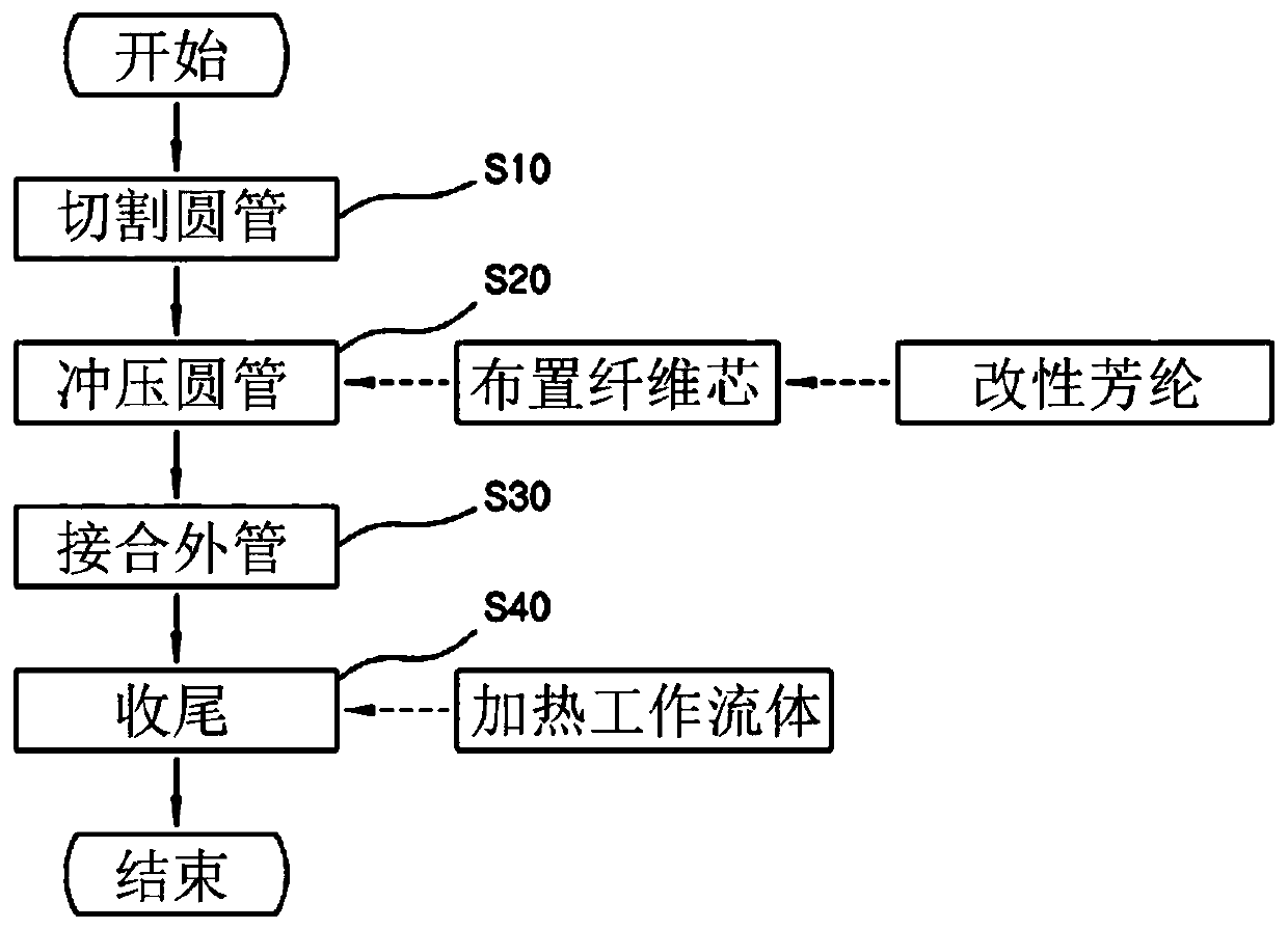
[0040] Such as figure 2 As shown, the heat pipe manufacturing method using the pipe body of the present invention generally includes: a cutting step S10 , a punching step S20 , a joining step S30 and a finishing step S40 .

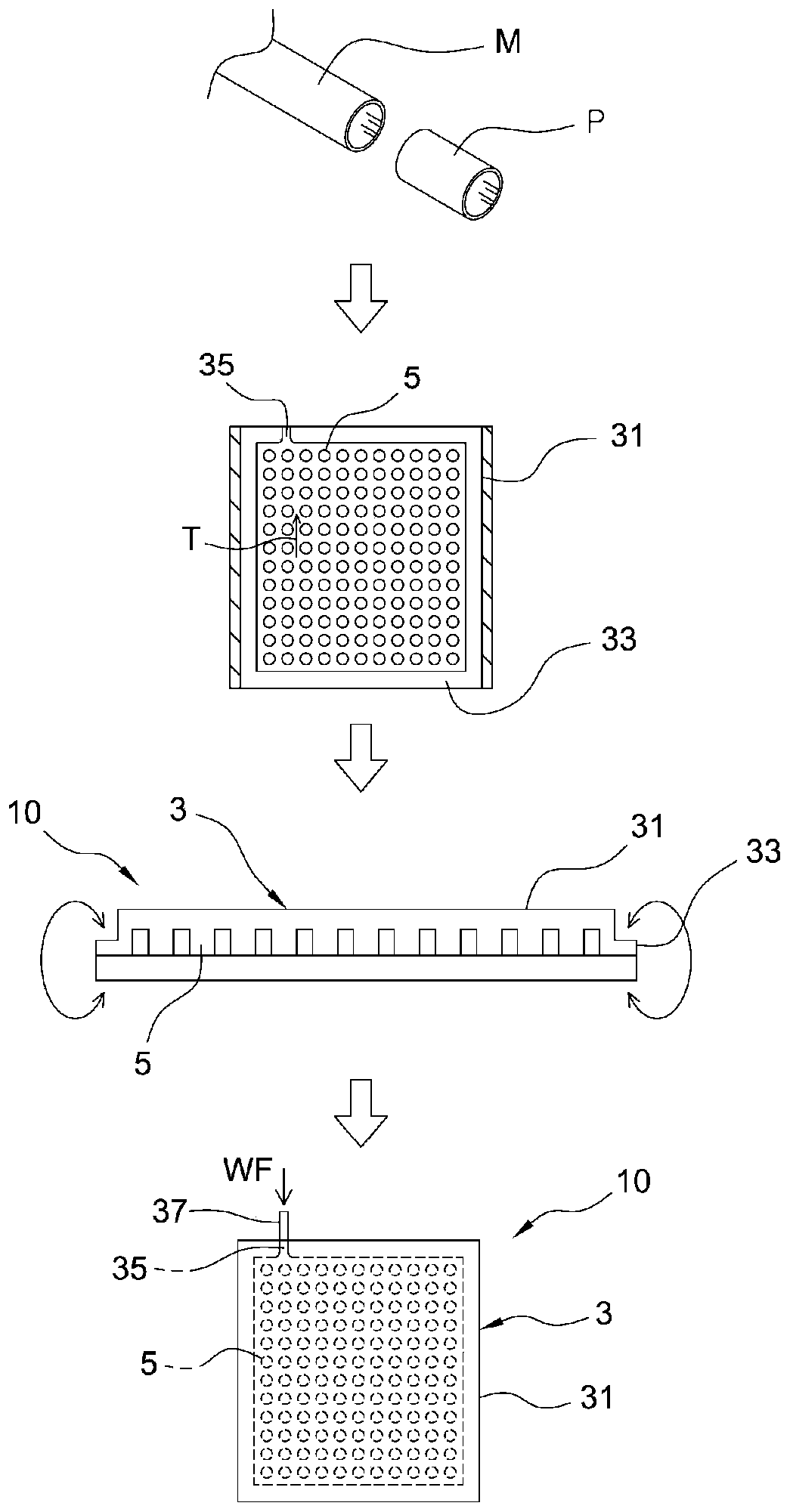
[0041] Such as figure 2 As shown, the cutting step S10 is a step of cutting a round pipe P from a metal pipe M. Such as image 3 As shown, the tubular metal pipe material M is cut to an appropriate length according to the outer pipe 31 constituting the casing 3 . Here, the round pipe P may be a closed-loop cross-sectional shape of various shapes such as a cylindrical pipe, an elliptical cylindrical pipe, and a square pipe. Then, if Figure 3 to Figure 5 As shown, the round pipe P is the outer pipe 31 . However, for the metal pipe...


PUM


Abstract

Provided in the present invention are a thin plate-type heat pipe using a pipe body and a method for manufacturing same, comprising the steps of: manufacturing a circular pipe by cutting a metal pipematerial; press-processing the circular pipe while a moving frame is inserted into the circular pipe to form a plurality of protrusions on the inner surface of the circular pipe, so as to form a throttle way between the plurality of protrusions; forming a wick space by press-processing the circular pipe while the moving frame is inserted into the circular pipe; arranging, in the wick space, a fiber wick comprising aramid fiber which has been reformed to be hydrophilic; forming a housing by closing the two ends of the circular pipe while the fiber wick is arranged; and injecting, into the housing, a working fluid flowing through the throttle way through an injection port, rendering the inside of the housing into a vacuum state through the injection port, and then sealing the injection port.

Description

technical field [0001] The present invention relates to a thin-plate type heat pipe using a pipe body and a manufacturing method thereof. Background technique [0002] Generally, a heat pipe is a heat transfer mechanism having a thermal conductivity several tens of times higher than that of a thermally conductive metal. Recently, it is being developed into a thin plate shape to cool the heat sink with a large area, such as the CPU of a computer. The thin plate heat pipe is usually made into figure 1 Shape shown (Granted Patent No. 10-0698462). [0003] Such as figure 1 As shown, the thin-plate heat pipe 101 is composed of an outer shell 103 and a core structure 105. The outer shell 103 is formed by laminating an upper plate 131 and a lower plate 132. The core structure 105 passes through the working fluid contained in the shell 103. A supporting structure 107 such as a mesh and a screen is formed in the housing 103 . [0004] Since the heat pipe 101 utilizes a fiber aggr...

Claims


Application Information

Patent Timeline
IPC IPC(8): H05K7/20F28D15/02H01L23/427
CPCF28D15/0233H01L23/427H05K7/20336
Inventor 尹护燮
Owner CGI SRL
Why Eureka
Try Eureka