
Patsnap Eureka
For R&D, Patsnap Eureka makes reading and utilizing patents & technical documents easy.
Patsnap Eureka AIR
Designed for self-driven R&D workflows. Generate viable solutions, solve complex R&D challenges, empower your innovation with AI.

Patsnap Eureka Materials
Designed for material experts only. Revolutionize your material R&D, from search, analyze, to developing new materials.

TechResearch
Generate reliable direction feasibility study reports for your R&D in just a few steps.

TechSeek
Discover and master advanced knowledge NOW. Basics, ideas, possibilities, all at once.

TechMind
As an expert in R&D Theories, TechMind can generates customized viable solutions instantly.

TechRisk
Analyze your overall solution with one click, know your potential R&D risks in advance.

TechMonitor
Get weekly tech updates, stay abreast of the latest tech innovations and key insights.
Movable sprinkling irrigation machine
A sprinkling irrigation machine and mobile technology, which is applied in the field of mobile sprinkling irrigation machines, can solve the problems of high equipment cost, and achieve the effects of low cost, easy maintenance, and simple structure realization
- Summary
- Abstract
- Description
- Claims
- Application Information
AI Technical Summary
Problems solved by technology
Method used
Image

Examples
Embodiment 1
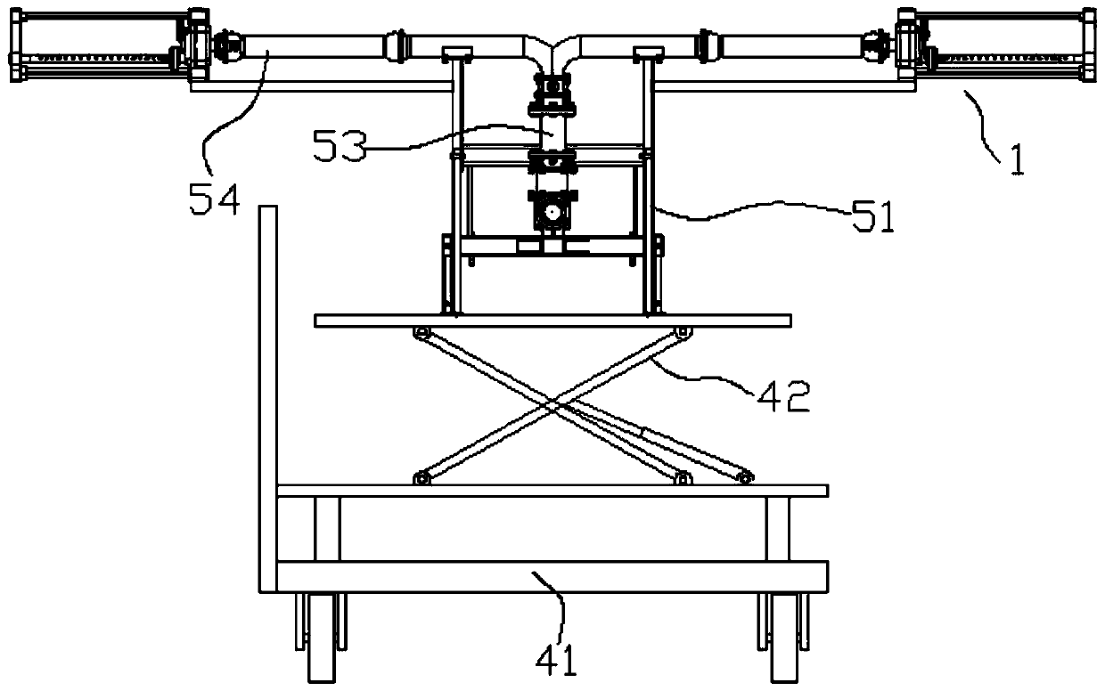
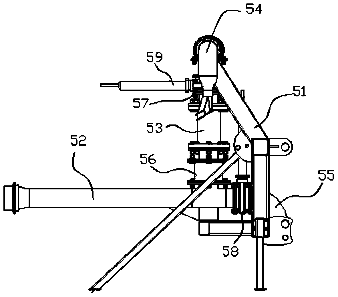
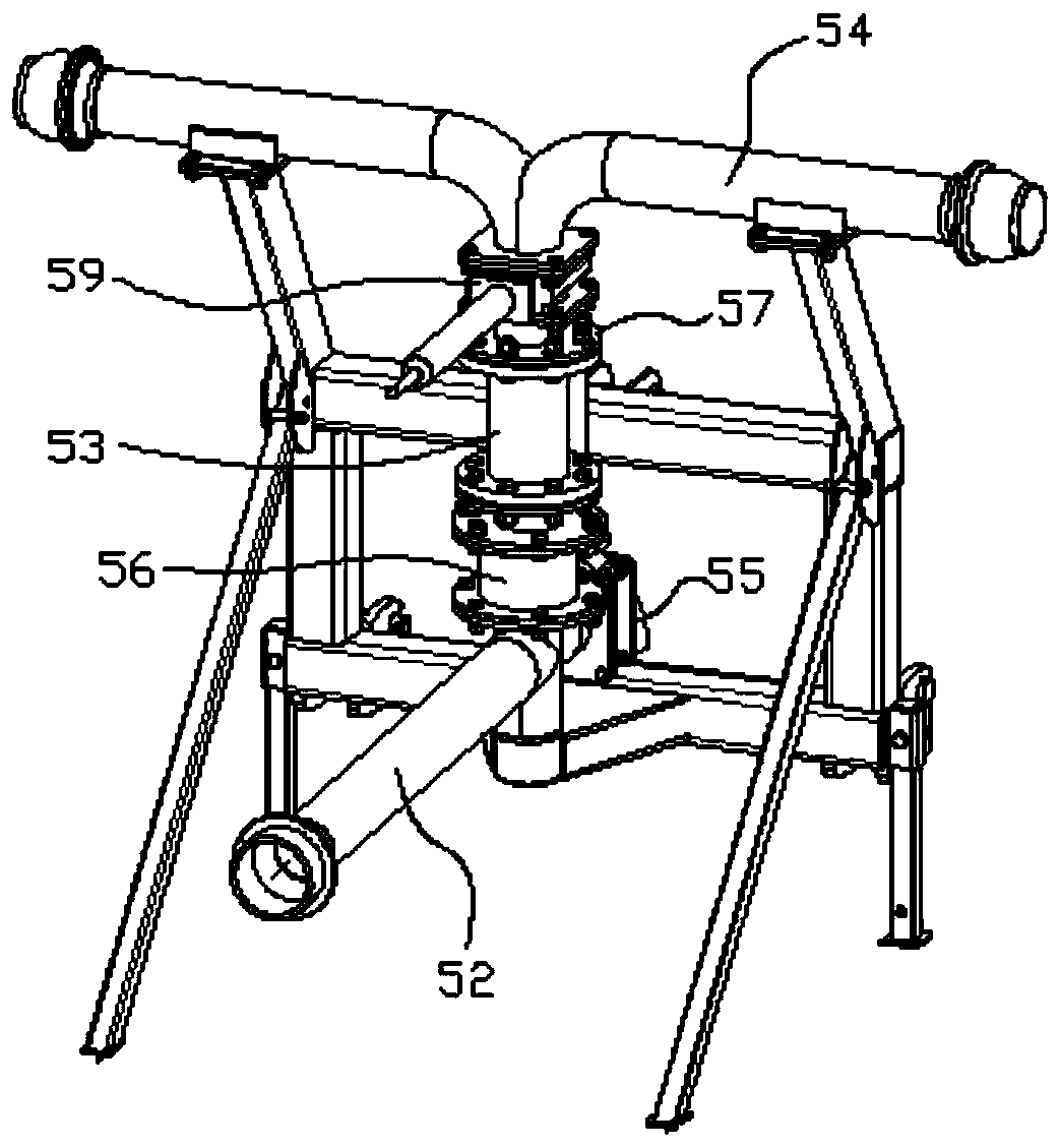
[0033] Such as Figure 1 to Figure 8 , a mobile sprinkler irrigation machine according to the present invention, comprising a walking frame 41, a scissor lift 42, a sprinkler irrigation frame 51, a water inlet main pipe 52, a water diversion main pipe 53, a water diversion branch pipe 54, a water outlet pipe 55, a first three-way pipe 56, The second three-way pipe 57 , the first on-off valve 58 , the second on-off valve 59 and the rotary nozzle unit 1 .
[0034] The scissor lift 42 is fixed on the walking frame 41, the sprinkler irrigation frame 51 is fixedly connected to the free end of the scissor lift 42, the first three-way pipe 56 and the second three-way pipe 57 are all fixedly connected on the sprinkler irrigation frame 51, and the first The three ports of the three-way pipe 56 are respectively sealed and connected to the main water inlet pipe 52, the water outlet pipe 55 and the water distribution main pipe 53, the first on-off valve 58 is connected to the water outlet...
Embodiment 2
[0050] Such as Figure 9 , The nozzle 12 in this embodiment is a horizontal structure, and the nozzle 12 is made of a metal pipe, and several nozzle holes are arranged in the circumferential direction of the nozzle 12 . The two ends of the spray pipe 12 are provided with a horizontal connecting section 121, and the horizontal connecting section 121 is provided with a stepped surface for bearing positioning. The horizontal connecting sections 121 at the two ends of the spout 12 are correspondingly connected to the installation frame 11 and the kettle 13 through bearings for rotation. In order to ensure the sealing between the nozzle 12 and the water inlet 13 , a sealing ring is provided between the horizontal connecting section 121 of the nozzle 12 and the water inlet 13 .
[0051] The other structures in Embodiment 2 are the same as Embodiment 1 and have the same performance and effect, and will not be repeated one by one.
[0052] The nozzle pipe 12 in this embodiment is a ...
PUM
 Abstract
Description
Claims
Application Information
 - R&D Engineer
- R&D Manager
- IP Professional
- Industry Leading Data Capabilities
- Powerful AI technology
- Patent DNA Extraction
Browse by: Latest US Patents, China's latest patents, Technical Efficacy Thesaurus, Application Domain, Technology Topic, Popular Technical Reports.
© 2024 PatSnap. All rights reserved.Legal|Privacy policy|Modern Slavery Act Transparency Statement|Sitemap|About US| Contact US: help@patsnap.com