High-safety sitting and standing work chair
A high-safety, work chair technology, applied to chairs, chairs with vertically adjustable seats, stools, etc., can solve the problems that the user cannot lean on the back, the chair cannot be installed with the back, and it is difficult to meet the requirements of standing in the office. It achieves the effects of convenient and rapid conversion from sitting to standing, simple structure and easy operation
- Summary
- Abstract
- Description
- Claims
- Application Information
AI Technical Summary
Problems solved by technology
Method used
Image
Examples
Embodiment 1
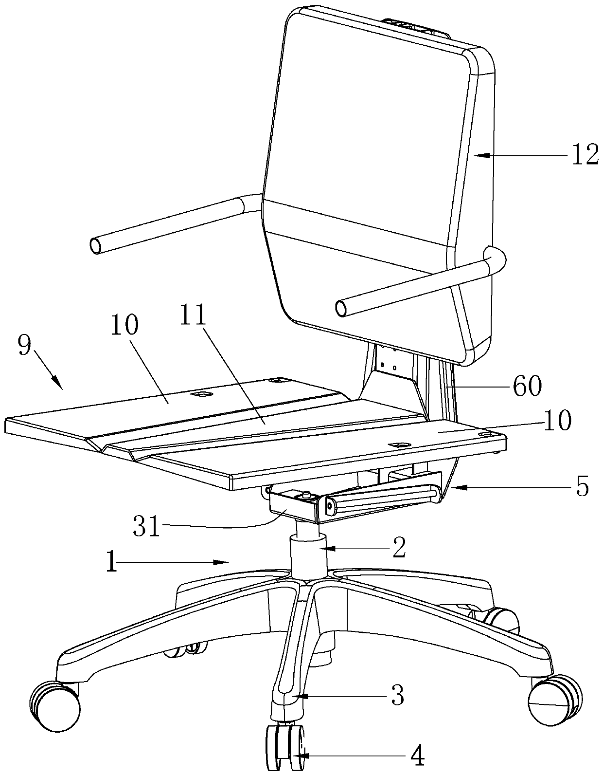
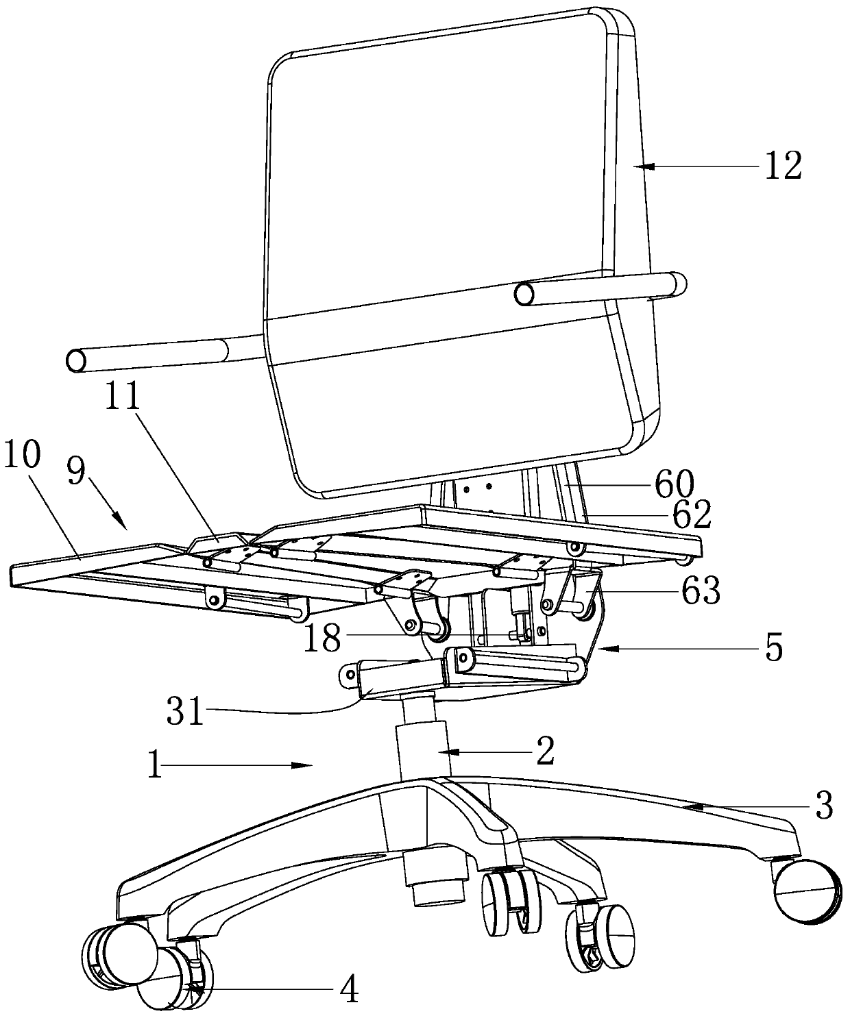
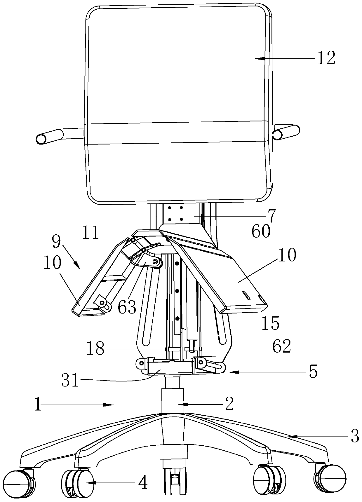
[0093] Embodiment 1: work chair of the present invention, as Figure 1-10 shown, including:
[0094] Seat support assembly 1, said seat support assembly 1 includes lift air rod 2, and the lower end of lift air rod 2 is plugged with support foot 3 with roller 4 at the bottom.
[0095] The base 5 above the ground is supported by the seat support assembly 1, and the base 5 is plugged with the upper end of the lifting air rod 2, and the height of the base 5 from the ground can be controlled by the lifting air rod 2. In this embodiment The height is set to 360-550cm; 400cm is the suitable height for most people.
[0096] The slide rail assembly 6 standing on the base 5, the slide rail assembly 6 has a moving rail 7 and a static rail 8 that are slidably matched with each other, wherein the static rail 8 and the base 5 are fixed by welding or connected by fasteners.
[0097] The seat support member 9 provided on the front side of the slide rail assembly 6; the seat support member 9...
Embodiment 2
[0116] Embodiment 2: as Figure 11-16 , Shown in 20-23, 33-36, differ from embodiment 1 in that, the present embodiment is not provided with lever arm 63, but adopts four-bar linkage to guide.
[0117] Specifically, this embodiment also includes a first connecting rod 64 and a second connecting rod 65, one end of the first connecting rod 64 is hinged to the first seat 11, and the other end of the first connecting rod 64 is connected to the second connecting rod 65. One end is hinged, the other end of the second connecting rod 65 is hinged with the second seat 10, the first connecting rod 64, the second connecting rod 65, the second seat 10 and the first seat 11 form a four-bar linkage mechanism, and the guide shaft 61 is arranged on the first connecting rod 64 .
[0118] In the four-bar linkage mechanism, the first seat 11 is stationary, and when the guide shaft 61 is guided by the chute 60, the first link 64 and the second link 65 are linked to drive the second seat 10 to tu...
Embodiment 3
[0122] Embodiment 3: as Figure 16 , 37 As shown in -42, the difference from Embodiments 1 and 2 is that the base 5 of this embodiment adopts a tilting chassis, so that not only the initial height of the base 5 can be adjusted normally, but also it has a tilting position when sitting flat. function to make sitting more comfortable.
[0123] Specifically, the base 5 includes a seat body 31 and a seesaw 32 that is rotatably connected to the seat body 31. The static rail 8 is fixedly connected to the seesaw 32. The upper end of the lifting air rod 2 is connected to the seat. The body 31 is plugged and fitted, and a return spring 68 is provided between the seesaw 32 and the seat body 31 .
[0124] A safety lock control mechanism is provided between the base 5 and the first seat 11, and the safety lock control mechanism includes a lock plate 69, a mounting base 70, a slide pin 72, a torsion spring 73 and a lock pin 74, and the lock plate 69 is fixedly arranged On the seat body 3...
PUM
 Abstract
Description
Claims
Application Information
 - R&D
- Intellectual Property
- Life Sciences
- Materials
- Tech Scout
- Unparalleled Data Quality
- Higher Quality Content
- 60% Fewer Hallucinations
Browse by: Latest US Patents, China's latest patents, Technical Efficacy Thesaurus, Application Domain, Technology Topic, Popular Technical Reports.
© 2025 PatSnap. All rights reserved.Legal|Privacy policy|Modern Slavery Act Transparency Statement|Sitemap|About US| Contact US: help@patsnap.com


