Milling cutter disc used for plate machining

A technology of sheet metal processing and milling cutter discs, which is applied in the direction of milling cutters, metal processing equipment, manufacturing tools, etc., can solve the problems that the milling cutter discs cannot be disassembled, the milling cutter discs do not have chucks, and the milling cutter discs cannot be fastened. To achieve the effect of convenient replacement, quick fixation and reasonable design

Inactive Publication Date: 2020-01-14
CHANGZHOU NAIZHILI TOOLMAKING
View PDF0 Cites 0 Cited by
  • Summary
  • Abstract
  • Description
  • Claims
  • Application Information

AI Technical Summary

Problems solved by technology

[0003] Therefore, a milling cutter head for sheet metal processing is needed to meet the current market demand. Although a variety of milling cutter fixtures have been produced on the market, in general, there are still many common problems. Firstly, the existing milling cutter head does not have a chuck, which makes it inconvenient to quickly connect with external components. Second, the bottom of the existing milling cutter head is non-detachable, which makes it impossible to replace the milling cutter head. Three, the bottom of the existing milling cutter head is only provided with one or two connecting screw holes, resulting in the inability to fully tighten the milling cutter head

Method used


Image

  • Milling cutter disc used for plate machining
  • Milling cutter disc used for plate machining
  • Milling cutter disc used for plate machining

Examples


Embodiment Construction

[0016] The following will clearly and completely describe the technical solutions in the embodiments of the present invention with reference to the accompanying drawings in the embodiments of the present invention. Obviously, the described embodiments are only some, not all, embodiments of the present invention. Based on the embodiments of the present invention, all other embodiments obtained by persons of ordinary skill in the art without making creative efforts belong to the protection scope of the present invention.

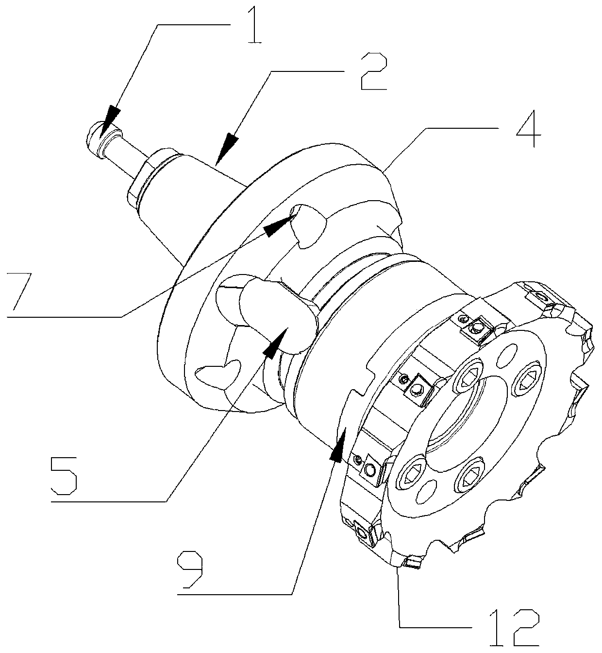
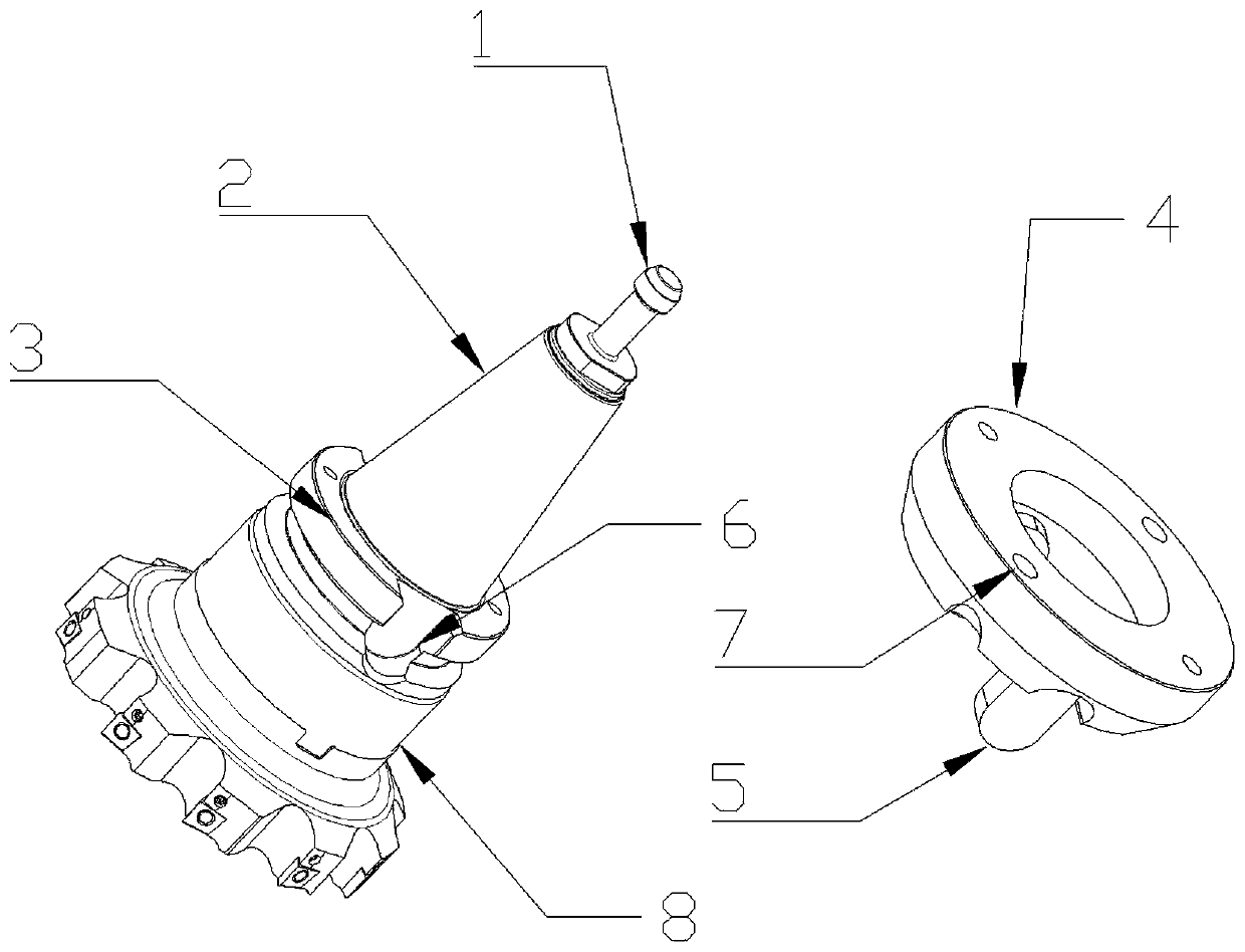
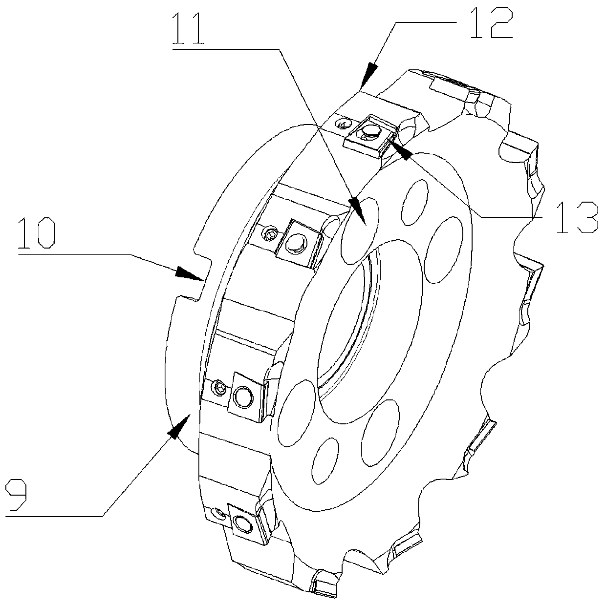
[0017] see Figure 1~3 , a milling cutter head for plate processing, including a limit column 1, a connecting column 2, a limit ring 3, a chuck 4, a block 5, a first buckle groove 6, a connecting screw hole 7, and a fixing column 8 , docking column 9, second buckle groove 10, fixed screw hole 11, milling cutter disc 12 and milling cutter slot 13; described limiting column 1 is fixed on the top of connecting column 2, and described connecting column 2 is vertic...


PUM


Abstract

The invention discloses a milling cutter disc used for plate machining. The milling cutter disc comprises a limiting column, a connecting column, a limiting ring, a chuck, a clamp block, a first buckle groove, connecting screw holes, a fixed column, a butt-joint column, a second buckle groove, fixed screw holes, a milling cutter disc body and milling cutter clamp grooves. The milling cutter disc has the beneficial effects that inward concave type screw holes are formed in the bottom ace of the fixed column, the screw holes are in one-to-one correspondence to the fixed screw holes, and screws can penetrate through the fixed screw holes conveniently to be rapidly screwed with the fixed column; the butt-joint column is in butt joint with the fixed column through the second buckle groove, andthe screws penetrate through the fixed screw holes to be screwed and fixed with the fixed column; through the corresponding screw holes, rapid fixing between the butt joint column and the fixed columnis achieved, and fastening is guaranteed; and fixed clamp sheets are arranged on the milling cutter clamp grooves, a milling cutter can be extruded and fixed through the clamp sheets, and the millingcutter can be conveniently replaced later through the manner of extrusion and fixing.

Description

technical field [0001] The invention relates to a milling cutter disc, in particular to a milling cutter disc for plate processing, and belongs to the technical field of milling cutter discs. Background technique [0002] Milling cutter refers to a kind of cutting tool whose arc length is greater than 1 / 4 circle. In mold processing, some small workpieces have a draft angle on the processing surface. Ordinary R angle cutters have relatively long blade lengths, and the rigidity of the cutting tool is relatively long. Reduced, the strength and rigidity of the tool cannot meet the requirements, and the service life of the tool is short. In order to strengthen the strength and rigidity of the tool and enhance the service life of the tool, a short-edged strong milling cutter is designed to improve the rigidity and strength and ensure the precision of the mold. , the mold is processed in place at one time. When machining the hole of the workpiece, the hole is generally rough-machin...

Claims


Application Information

Patent Timeline
Patent Type & Authority Applications(China)
IPC IPC(8): B23C5/08
CPCB23C5/08
Inventor 李志芬梅永杰
Owner CHANGZHOU NAIZHILI TOOLMAKING
Why Eureka
Try Eureka